
-
Visit our website www.piratehorizons.com to quickly find download links for the newest versions of our New Horizons mods Beyond New Horizons and Maelstrom New Horizons!-
Join our discord server for regular podcasts/AMA about upcoming and released pirate games (Caribbean Legend, Corsairs Legacy, Ahoy, ERAS 2, etc.):

-

Quick links for Beyond New Horizons
- Download latest version
- Wiki - FAQ - Report bugs here - Bug Tracker on Github -

Quick links for Maelstrom
- Download the latest version of Maelstrom
- Download the latest version of ERAS II - Download the latest version of New Horizons on Maelstrom
-
Join PiratesAhoy! on our social channels:


-

Quick links for PotC: New Horizons
- Download latest version
- Wiki - FAQ - Report bugs here
-

Thanks to YOUR votes, GOG.com now sells:
- Sea Dogs - Sea Dogs: Caribbean Tales
- Sea Dogs: City of Abandoned Ships
Vote now to add Pirates of the Caribbean to the list! -

Quick links for AoP2: Gentlemen of Fortune 2
- Downloads and info
- ModDB Profile
- Forums Archive -

A Pirate Podcast with Interviews
Music, Comedy and all things Pirate!
- Episode Guide - About - Subscribe -
- Twitter - Facebook - iTunes - Android -
- Youtube - Fill the Coffers -
(0) Hearts of Oak - Model- & Texturhandling
- Views Views: 611
- Last updated Last updated:
-
Last time edited: 9. May 2014
[1] Hearts of Oak - Modeling Guideline
When creating a model for "Hearts Of Oak", you should focus the overview below, to get the result you want and ensure that your model fits well in the game world, with other modelers' content.
Based on Maya, the most important creation rule is, for every material you want, to setup it's own submodell inside your model. Example: You have a wooden stick or tree trunk with some metal elements, like a lamp. The model is in this case called "lamp". The "lamp" contains 2 submodels: wooden and metal parts. To give them their own texture, you need these two parts separately as submodels inside the mainmodel. Mainmodel is in this case the CRYEXPORTNODE or better said: Top group (node), that gives the model name later.
Note: I can ever write this from my eyes as Maya-modeller.
When there are multiple parts of the same surface type, for ex. metal, you can combine them together. That means: The metal cage of the lamp have 4 separate, curved spikes, you can combine that all into one object. Which will be the metal submodel.
Short:
- Normally you have a CRYEXPORTNODE, that's the top group of your file. You will see this in the other WIKI entries much.
- Under this CRYEXPORTNODE are placed the parts- and LOD- groups. The design depends on the modeling program you use. Please remember: All I write is based on Maya.
- When exported later, open the material editor in Cryengine and grab your .mtl from the list. If you don't have a .MTL, please copy an existing one and erase all entries with notepad or norepad++ or if your modeler supports the .mtl export feature, use this. Take then ever our games standard roots!
Your textures must be placed ever in
objects/heartsofoak/textures
When you have found your MTL in the list of the CryEngine Materialeditor, you will see that it maybe can contain only one material or more submaterials you need. Make a mouse right click at the MTL entry in the list and chose "set number of Submaterials". Chose the number of needed submaterials.
Then you have your .mtl with two or more submaterials (for our example). Every Submaterial is the child for every part in the model. For example:
1. All wooden parts, combined to submodel 1
2. All metal parts, combined to submodel 2
Note, that the Diffuse texture inside a Submaterial is the same for all submodell that use it. If you have 2 types of metal (2 textures (for example: one new, one rusty)) then you need a third submaterial (you must have in this case a third submodel too). The CryEngine supports 32 submaterials in one model. Models can be attached together in the CryEditor, so if you need more, attach simply two or more model parts to one big model. Mostly ships or castles.
When you have the submaterials you need, you can setup them individual inside its settings. Means: Diffuse and Specular color, parallax occlusion mapping, dirt texture etc. pp..
Diffuse color brings me to another important info: We use texture sharing. It's important to use it! Create so less textures as possible and make them individual looking using diffuse colors and different dirt textures and setup. Most different UVs give good results for individual look too. Its a little bit of get skill and practice to make the models real good looking and individual. When we have for example 20 textures for wood in the collection of all Hearts Of Oak textures then you can use them at your model if need. Need you for example a new one, in later game process when we create and sort the texturebase better and better, we have all a conversation about texture handling.
"Textures:" When create own textures, please ever create tiled, high resolution ones in the "power of 2". Means: 1, 2, 4, 8, 16, 32, 64, 128, 256, 512, 1024, 2048, 4096, 8192, 16384
Actual our highest compromise of sharp texture and filesize is 4096.
Textures will be stored in CRYTIFF (after installing CryTools an available option in Photoshop). You can place the textures as CryTiff then into the
objects/heartsofoak/textures
root and set them in the CryEngine materialeditor in the channels. The engine now compiles the DDS (compressed formats) by itself. When saving textures as CryTiff, please ever use the HighQ method with the option "BILINEAR FILTER". The naming of WHAT you are saving is clear in the option. Diffuse, Normal etc. are clearly named. This part I explain better later in this "(0) Hearts of Oak - Model- & Texturguideline".
The "Performance and Economical Rules":
Note: When ever you create Assets, please create them good looking and NOT too sparing with polygones BUT see exactly to the weight what "economical" means! In this case many, MANY stubborn opinions haunts around and we need to clear it here.
It is important to always mind the following things:
1. We create a future-proof game and everyone of you will only create one time an model. You and we will save frustration and more work when you are too economical or too wasting with polycount and details. So create them good real looking and detailed but with focus to the follow "important economical rules".
2. To create wise and economical means: Create them real nice but NOT waste polygons. Example: A tree trunk have actual 8 edges. Thats too low. 8 is noticeable in-game and looks like an model from year 2000. When you chose 16 or 24 edges at LOD0 (rendermesh) you have a real smooth and good looking one. If you chose 32 edges, its wasting. No one see the difference ingame between 24 and 32 edges around the model. In very rare situations, like a ships steering wheel, you need test this out with a dummymodel and can chose higher polycounts. Take the time to test with dummyexports in different stages. Often you are wondering yourself where the border of noticeable polycounts are located.
IMPORTANT: In face of reduce polygones later, pease create ever for example the diameter edgeloops or round parts in the "power of 2" too. When reducing polycount, normally you delete every 2nd loop. You need to fit this to the final 4 left loops later. When creating all other parts, hold ever the later reducing in your head and think about the LODs when creating your rendermesh.
3A. Here follows the next step: After creating the good looking (not polywasted or too economical) created rendermesh, you start the compensation of it with the LODs. Every LOD-step is a ca. 50% reduced polycount of the further mesh. This depends of the type of your model. At ships we blend off with LOD1 all interior and reduce polycount at all other parts, so mostly LOD0 (rendermesh) to LOD1 save more then 65 - 70% polygons. To repeat the example of a "tree trunk"-mesh means this:
LOD0 - rendermesh, for example with 16 loops. I think at a small wooden part 16 is the one you didnt see as edges with your eye in ingametest. If the round shaped object becomes bigger, try 24.
LOD1 - 8 edgeloops but no reduce or small reduce without big influence to its curved shape, the vertical edgeloops.
LOD2 - 4 edgeloops and reduce the vertical ones but left the most defined curves for the main shape in place.
LOD3 - 4 or maybe test 3 edgeloops (depends to the ingametest). The most noticeable shape loops you can reduce here too (depends to the ingametest).
Vertically placed edgeloops for shaped or curved looking, mostly starts with LOD2 in reduce them because for the human eye the step LOD0 to LOD1 can be noticeable, LOD1 to LOD2 unlikely. Test this in-game after export. Please test this ever by yourself in-game with a test of your model!
LOD debugging: Type in the console: e_debugdraw 1
Set for LOD-debugging after placing the model in-game the LOD-range to 255. That means fastest switch. 100 (standard) means later switch!
Test now 2 things:
3A.1. With "e_debugdraw 1" (means enabled) if the model shows the right polycount and naming for each LOD-step. LOD0 always means the rendermesh.
3A.2. When 3A.1. works and you see the debug screen switches the LODs right, set e_debugdraw to 0 and see if your eye notice the LOD-switch in noticeably way. Small notice is no problem, because the later LOD range is bigger.
3B. Think about LOD-creating techniques:
3B.1. You create for example a furniture part, detailed but not too detailed (without bevels and other finer details etc.). This you NEED to take as LOD1. Short: When you create it without bevels, take the mesh as LOD1, copy it and bevel it more fine and add other small finer details, to get this then as LOD0 (rendermesh). The reason behind this way (to create LOD1 first) is, that the reduce of such complicated LOD0 meshes to LOD1 (specially the bevel edges) is very, VERY heavy. Most UVs gets broken or you need to set the top of bevel edges together, to reduce it to its outer shape. A simple connection of the outer vertices wont work the way you want because the diameter of the object becomes smaller then. A bevel edge meets, with the option "connect vertex" ever in the half of both vertices between the bevel. So you must bring both vertices to the real center by hand. For every part you create, please think wise about its LOD1 or LOD0 first creating, based on this knowledge!
3B.2. For lots of parts you can create LOD0 (rendermesh) first. A mast for example. Create the edgeloops ever tileable to 4 in the power of 2 (for reducing edge loops later). Based on the above entry, please attention it what creating "economical" means. Those simpler shapes you ever create high detailed as LOD0 and break down to LOD1 simple in reducing edgeloops. Its a little bit of practice need to handle the LOD creating. For example the masts, LOD0 to LOD1 compared, LOD1 ever have 8 edgeloops, LOD2 have 4 loops. If like to do, then test the minimum 3 edgeloops. Ever remember that LOD0 to LOD1 is noticeable by human eye, LOD1 to LOD2 not really, LOD2 to LOD3 close to be impossible noticeable.
IMPORTANT: Reducing Edgeloops means ALWAYS that the mast (or other round shaped meshes) lose diameter! Test this ingame, if your eye notes the LOD-switches at LOD-range 255. AGAIN: For this, please set the LOD-range to 255 (fastest switch). 100 the standard value means later switch. The space in this range, from 100 to 255 is your save range. That mean: Small LOD switches you see will close to be impossible noticeable by eye in bigger LOD-ranges. Small notice of LOD switching is NO problem. Reducing Polycount you cant compenaste 100%!
When creating LODs always note, that for real big models like ship, you never need to create every part new and for every part a new LOD. Read wise: A ship have many common parts. For example at deck the wooden parts for the ropes etc.. You create one of it. Mostly the ship have at the upper deck around 30 till 40 wooden pieces. Chose the best way for LOD- creating (3B.1. or 3B.2.) and give them UV and normals. Copy both and (in Maya this works together) give them a new UV (most move or rotate inside UV-Space) and place at the new position. This way you have set a new modell and a new LOD with new UV together.
4. Till here you have create your modell with LODs. The next important economical thing is to give bigger modells own physical proxys. This means: Bigger and complex parts with polycount over around 10.000 will ever be physically calculated based on its rendermesh. So when you have a 17.000 polygon model, the physics is calculated on this count.
Create here a physical mesh. Mostly the lowest LOD as copy. That says the engine its physicalized. That relieve the GPU when scenes become very complex. Much important in big scenes!
To get this system working, you need two settings (I don't know the workflow in other tools, so I base on Maya):
4.1. You can give every part with the Cryexporter a flag. Normally the model itself have the "Physicalized flag." An other option are "proxynodraw" (physical proxy).
4.2. To reduce the physical calculation from your rendermodel, you need to set the option to "none". So no physicalisation will be calculated from the model itself. Do this for all model parts. Think about different exports of your modellparts and its attachment together inside the CryEditor because the physical proxy render ever the physics for the part, where it placed under in the hierarchy.
As example: You have a big chimney. The base is stone, the chimney itself are high detailed metal with many pipes and other parts. When you export both as one model, that contains both submodels (metal and stone) then you can only render physicalized effects like decals or destruction at the part, the physical proxy is placed under. So either stone OR metall. You can export only one physical proxy per model. So here the way is to export the chimney and the stonebase separately and give both parts the physical proxy.
This sounds wired but it is very simple. You need only a little bit practice in its handling.
5. Dont focus too many DX featured things like "Drawcalls". In contrast: Say them "goodbye". It is surely important to think about economical model creating (the 4 points above) but to fix the own work to a low poly level with knowledge from year 2010 is the WRONG WAY for Hearts Of Oak. An important example is AMD Mantle. You can use this with Nvidia too and it gives up till 70% better GPU handling. That should be result in an FPS plus of around 30%. The tech sheets and independent tests sound real great. CryEngine works very well with Mantle, that shows the tech forum for Star Citizen (Robert's Space Industries). Mantle didn't render with drawcalls. Till today its the best and most effective graphic interface we have. The next SDKs support Mantle. At the moment its real good to fix the performance ingame to DX and have a save range to Mantle as more relief.
6. Always think about TWO render intensive parts:
6.1. Frame Calculation. That is the Frame per Second. The most important and most observed factor for smooth gameplay...
6.2. BUT: The most unnoticed part is the physical engine of the renderengine. Parallel to the Frame per Second - thing a second engine (called the physical engine) calculates the influence of all parts in the gameworld to physical events. That mean: All what you see at the screen with FPS need to be physical rendered in some way. For example: Ship at the waves, cloth in the wind, grass and tree foliage in the wind...
In the past, this part was mostly bypassed to the CPU or could be set for individual games to GPU or CPU. Both options have Pros and Cons. Only systems with very big GPUs can setup the physical calculation to the GPU, because in cost of frames, normally a big GPU have enougth, the GPU renders the physical events much faster. Lower Systems gets here a diashow.
6.3. The other part was to render ever the physical influence at the CPU but for this part, the GPU must calculate the data-exchange between GPU and CPU aaaand the CPU is never so optimized for this part as a GPU. Often here the BUS at the Motherboard was the bottleneck for the data exchange. Here you can see the reason why ever new systems was tested and things like "physical cards like PhysX" was born.
A very good example is the Entity "cloth" in the CryEngine. Its cloth simulated at very high quality but you can crash at !60FPS! the physical engine part with only 10 sails at a dynamic object. You have 60FPS but you see the ship and its sails stottering. Thats the price of realtime rendering. It exists many other techniques but it shows how important it is to think about physical proxies at bigger parts!
Modern engines try to handle most of it in multi-GPU and Multi-CPU calculation with many, many tweaks and renderthreads. Normally you ever hit this physical border first in modding or game creating, before the FPS comes down to 25 or 20. Testmaps at max quality with many, many overload content brings here the results of driver setup, the own system power and chosen grafical interface (DX or Mantle).
For HoO we have tested so far an overkill setup at 13 million polygons. You NEVER hit this count in the game. CryEngine 2 (16 million) and CryEngine 3 (12 million) shows the actual border of FPS and physical engine as border. Most this can change dramatically with special systems like cloth at dynamic objects. For this, only 100.000 polygons at the screen are enough. Too intensive are the needed calculations for real time cloth with all game environment influences PLUS the ship interaction. To find the actual real border we need to setup a full island with harbor and more then 10 full rigged ships, to find the deadline of what the engine can handle at one screen. We ALWAYS are looking for new or alternate techniques. The work behind the scenes of Hearts Of Oak is real big. The "Art" of game making is here the golden goal of using the economical rules so wise you can.
The detail tutorials for special modelsetups you will find in the next WIKI entrys. There are too many differences, I cant explain here inside this one text.
[2] Hearts of Oak - Textures Guideline
IMPORTANT: When you think, you need a texture, please EVER remember RULE 1:
Please take a look if you can use an existing one. The more textures (LARGE textures, for final quality) the game must load, the more grafics memory will be used!
To get the best compromise of texturesize (in MB) and its optical impression ingame, its need to take this (as best solution researched) setup:
When your diffuse texture is 4096 (what is large), please save its normalmap (DDN) in the same resolution and specular- and heightmap (displacementmap) in the half resolution. Many tests ingame show no difference between 4096 and 2048 specular- and heightmaps on used 4096 diffuse and normalmaps.
Summary when diffusemap = 4096 x 4096:
texture_diff = diffuse = 4096 x 4096
texture_spec = specular = 4096 x 4096
texture_ddn = bumpmap (normalmap) = 2048 x 2048
texture_displ = displacementmap (POM (~heightmap)) = 2048 x 2048
Summary when diffusemap = 2048 x 2048:
texture_diff = diffuse = 2048 x 2048
texture_spec = specular = 2048 x 2048
texture_ddn = bumpmap (normalmap) = 2048 x 2048
texture_displ = displacementmap (POM (~heightmap)) = 2048 x 2048
1024 x 1024, similar as 1024 x 1024 as 2048 x 2048 = All texture, same resolution 1024 x 1024 etc. pp..
Textures lower then 2048 means often less visual quality. In the focus for Hearts Of Oak futured quality, only a few textures can be smaller then 2048. It depends on WHAT the textures are. For example: Very simple fake reflections on later transparent windows etc. are OK so small. In this special region, you need to compare ingame by yourself at your modell or terraintexture, what quality fits best all the other referencecontent around.
The way of an texture to the CryEngine
Textures must be ever setup in the power of 2 in resolution. This means, that the size ever must be "x2":
1 x 1
2 x 2
4 x 4
8 x 8
16 x 16
32 x 32
64 x 64
128 x 128
256 x 256
512 x 512
1024 x 1024
2048 x 2048
4096 x 4096
8192 x 8192
16384 x 16384 (max texturesize)
When you let your view pass all the resolutions please note, the bigger the texture, the bigger the bottleneck at smaller systems because the faster the texturememory is filled till the top.
In all researches I have found out, the 4096x4096 as maximal size is the best compromise and looks real good ingame.
Lets go.
OK, you have your texture and want to get it ingame. At first, please remember the naming convention, I have written at the top of this textures guidline!
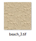
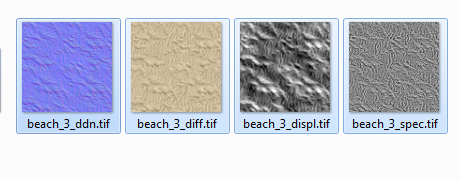
Example, your texture, named as "what ever", should be renamed WITHOU prefix but with the countnumber inside its field of application. My example is: "beach_3"
PICTURE
IMPORTANT: To have no lost in quality over the time of working at your texture, please EVER save in TIF without compression! Not in JPG or other formats! Later, the format "CryTiff" will overwrite with the same "*.tif" file extension as the base file.
[2.1.] Creating the maps, you need
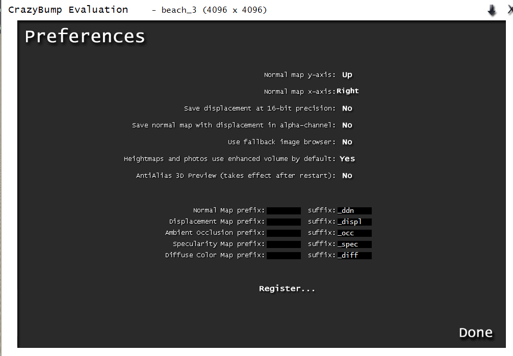
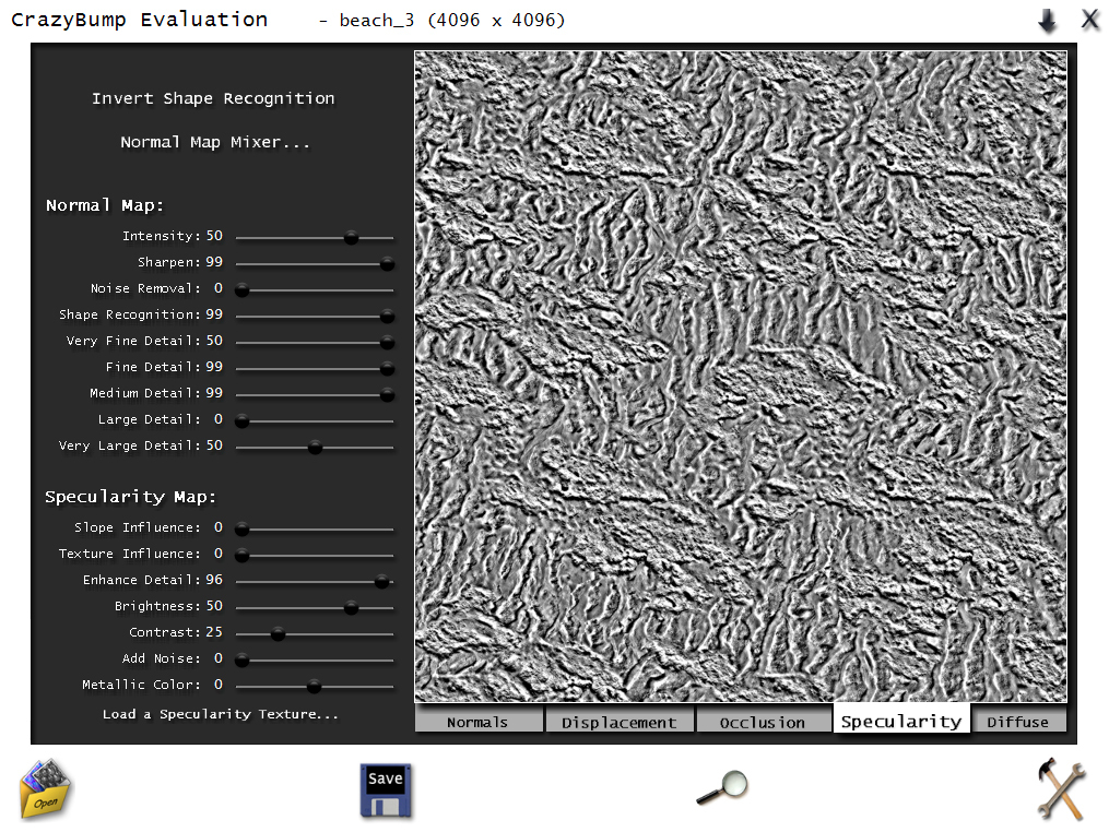
When you want to save time in creating the other maps by hand or many other tools, think about to buy "Crazy Bump" or use at first its evaluation version, with no restrictions.
Here, the settings I use:
PICTURE
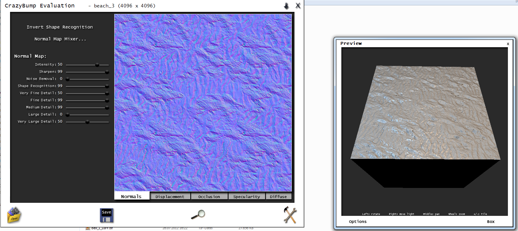
Load the texture into the tool and play around with the preview, what result you like. Note ever, that the look ingame is a difference to this preview! The preview is a "feeling" and good for shape recognition or the the sense of sharpen etc.. Mostly you start with the NORMALMAP:
PICTURE
When you have found a good looking result, please save the normalmap. You see, that the tool use automaticly the prefix "_ddn" from the settings for the normalmap. Now you understand why I have written to give your basetexture the final name but without any prefix.
PICTURE
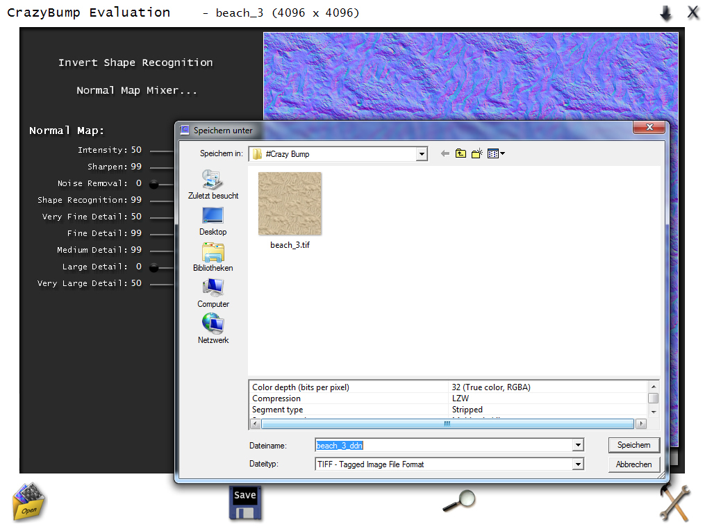
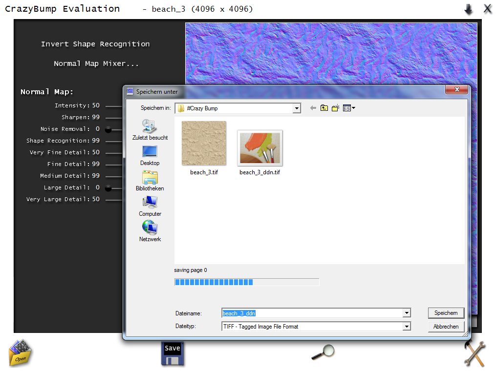
The saving, depends on the size of the texture, will be a while:
PICTURE
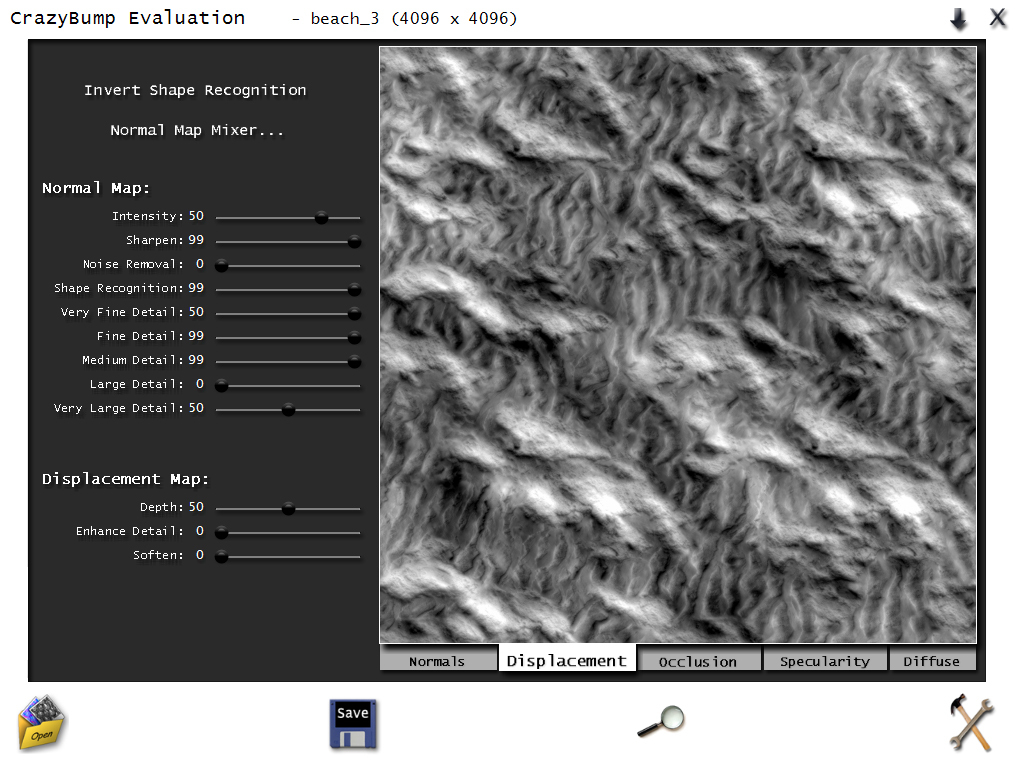
Please repeat the same for the DISPLACEMENTMAP (heightmap for Parallax Occlusion Mapping (POM))
PICTURE
And the same for the SPECULARMAP
PICTURE
Rename now your DIFFUSE-texture to the naming convention "_diff" and you should have this result now. Info: Its not important if the basetexture is already CryTiff or not. This "saving" you do in the next step!
PICTURE
Note, that you can create this maps the way you want. I show only the way with the tool "crazy bump"!
[2.2.] Resize the textures and save as Crytiff
For this step I use Photoshop.
Please remember the first section in this textures guidline! The size should be fit to the recommend setup and this means, that we need to resize the specular- and displacementmap. Every texture have a small
"unique" setting, so please NOTE THIS in the follow section!
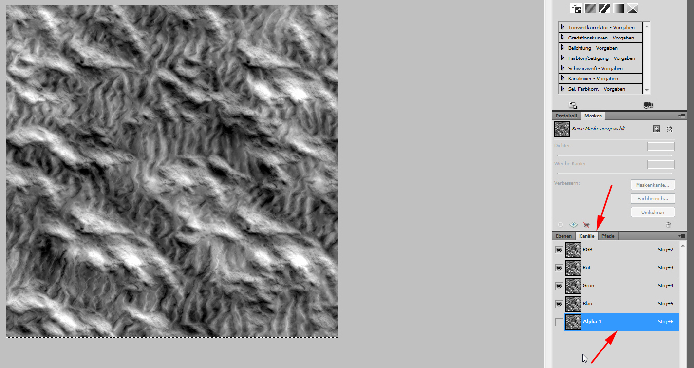
Open the first texture in Photoshop and chose "SAVE AS". This is important to get the CryTiff- AND Alphachannel option!
Our first texture is the DDN, normalmap or sometimes named "bumpmap". The real bumpmap is normally monochrome but ignore this naming doctoring. I think you know what we are talking about.
Please see exactly to the picture below. Crazy Bump or other tools save maybe empty alphachannels in the textured but when not used, the alphachannel waste much texturememory!
So, when you click "SAVE AS", the next window give you the setting "Alphachannel" by default.
PICTURE
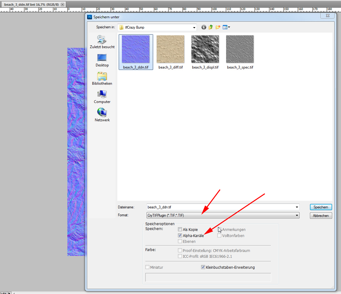
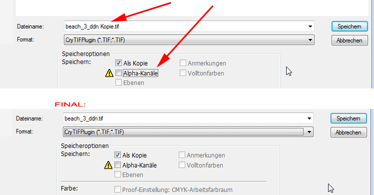
Please UNCHECK this option. In case of the same naming, Photoshop set "copy" behind the file name. Please delete this "copy", and overwrite your original texture!
PICTURE
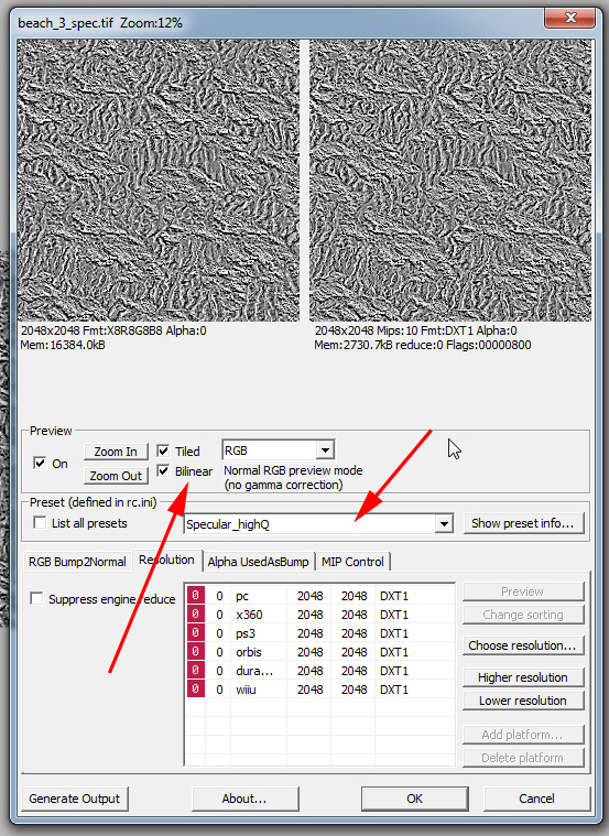
After clicking "save" (and "overwrite"), the CryTiff options menu comes up. Here you set the quality of the texture (ever to HighQ) and click to "BILINEAR".
In my example you see: Set Normalmap_lowQ to NORMALMAP_HIGHQ !
PICTURE
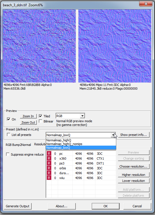
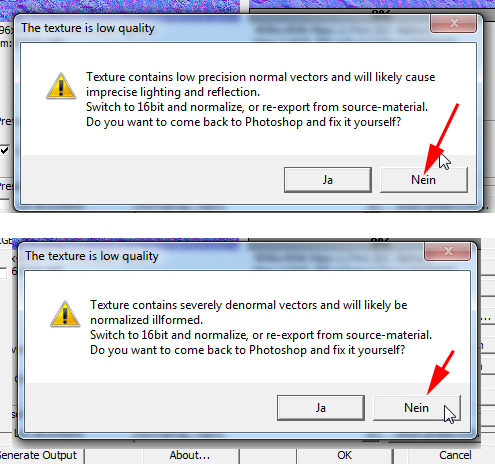
Sometimes, after changing the NORMALMAP quality to highQ, one or two messages apperas. Ignore both by clicking on "NO". Read, its NOT the same message")
PICTURE
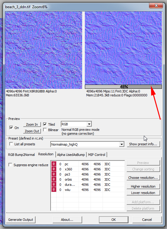
After clicking "no", the previewrendering will be a while. Please WAIT and do nothing or you get an rc.exe crash (ressource compiler).
PICTURE:
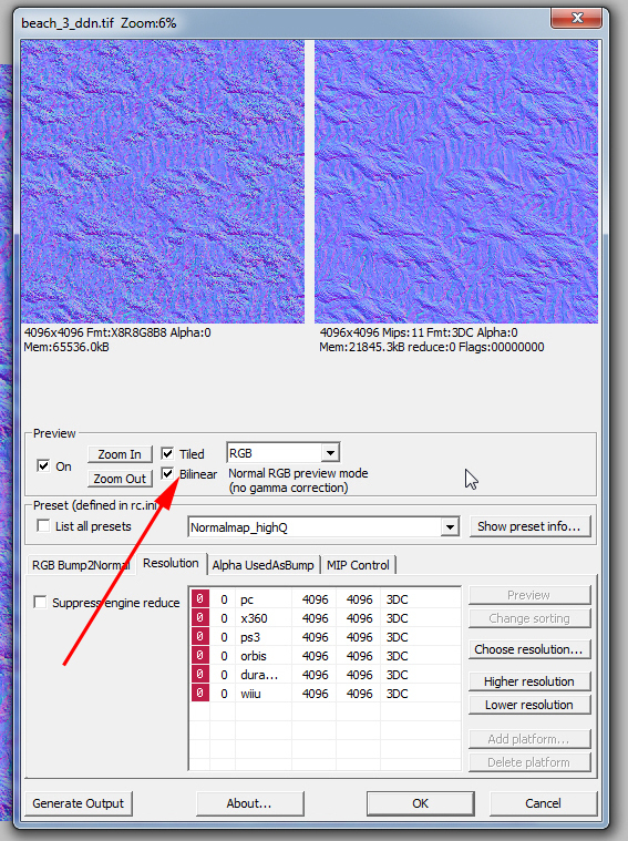
Please do not foget to set at last the setting "BILINEAR"
PICTURE:
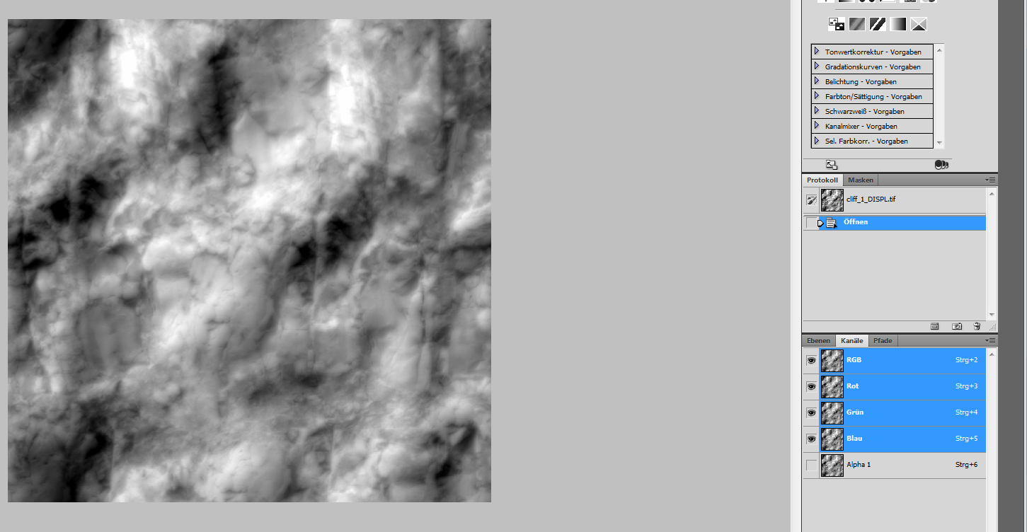
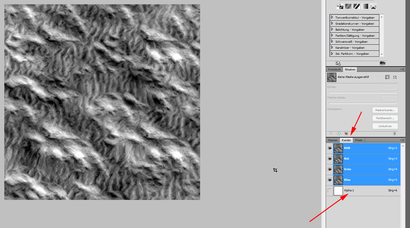
Now the DISPL, displacementmap or heightmap. The displacementmap is sometimes need to make surfaces more 3D plastic then a bumpmap / normalmap can do. what this means, you see at the follow pictures.
The technique behind the plastic illusion is named: PARALLAX OCCLUSION MAPPING (POM).
For this textures its important to save it with the same texture in ALPHAchannel!
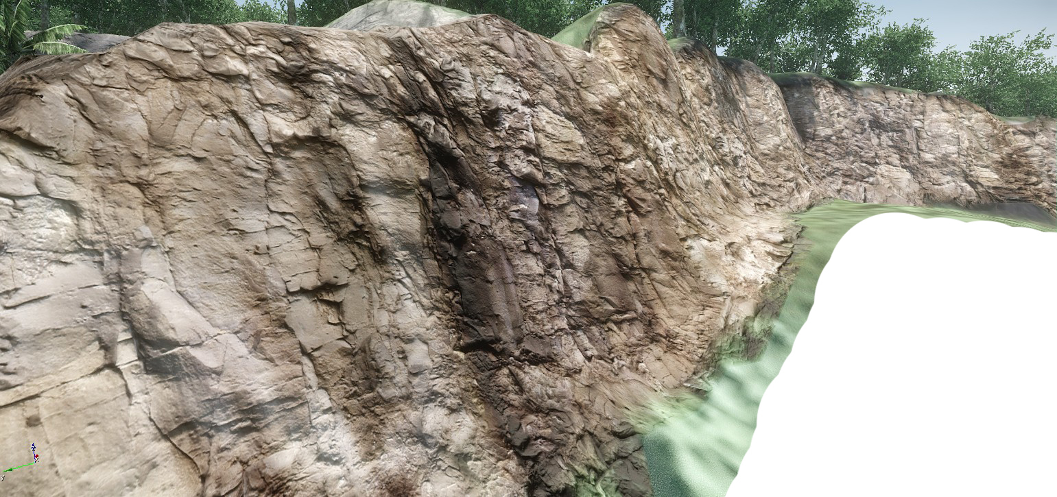
You see at the follow screenshot a rock with a POM texture setup and how the rock looks. It looks very cracky with rough surface but this illusion generates the "_displ" map at a flat surface.
PICTURE
Especially for this example, here the heightmap and its alphachannel in photoshop:
PICTURE
Another example of POM-map, depends on the settings in crazy bump and what you need the map for:
PICTURE
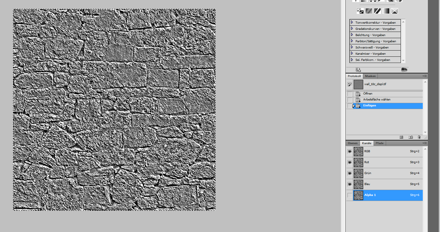
To grab the example like for the DDN, here the process in photoshop. Open the "_DISPL" map and copy the texture into the empty alphachannel.
PICTURE
PICTURE
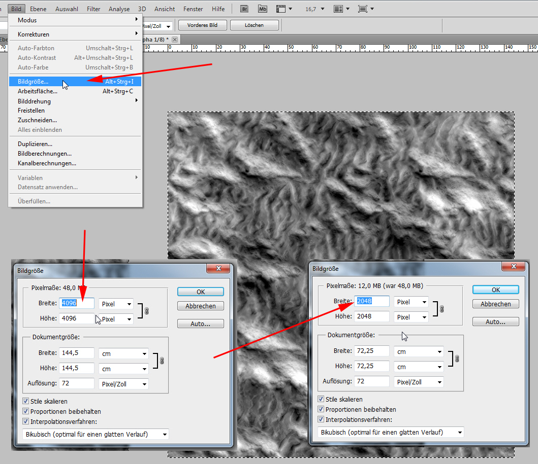
In the next step RESIZE the whole texture to the convention, you find at the top of the textures guidline.
Remember: Our base texture was 4096x4096 and now we need to resize the heightmap to 2048x2048!
PICTURE
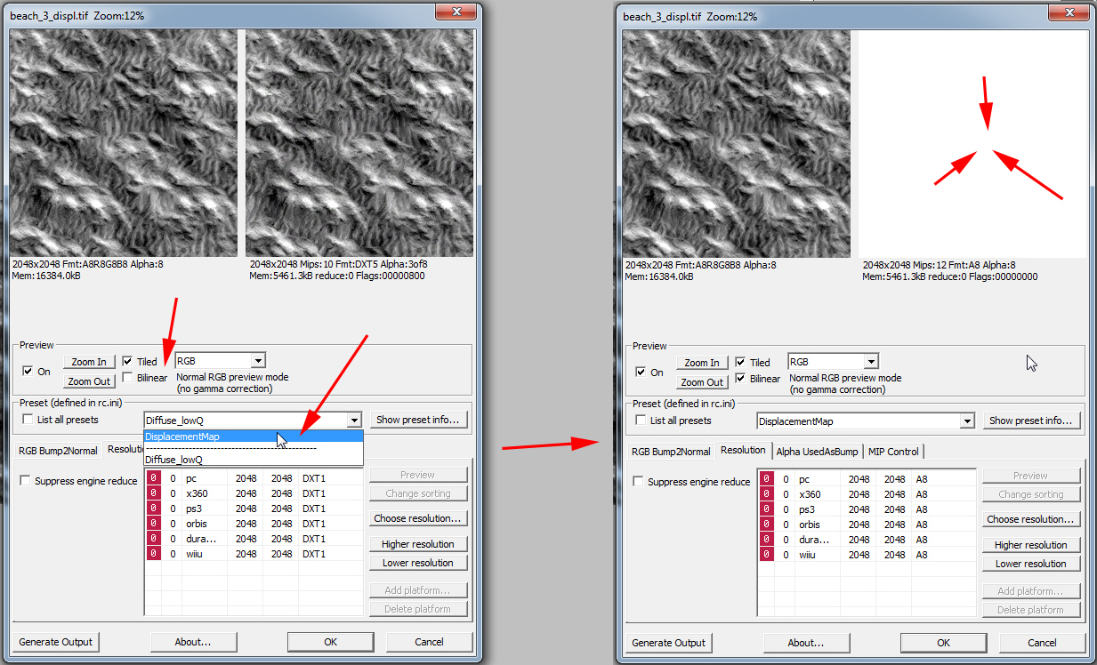
OK, now we are done. Please chose now "SAVE AS". For this texture WITH alphachannel! Overwrite the existing texture!
PICTURE

After clicking "SAVE" and "overwrite", set the CryTiff window settings you see below.
Change the preset to "DisplacementMap" and wait till the % of the preview window are done and set at last "BILINEAR". At displacementmaps, the previewwindow becomes white. Why ever, this is right!
IMPORTANT INFO: Please do never think its not important what PRESET you take! If this is LOWQ or HIGHQ or DIFFUSE, DISPLACEMENT etc.!!! ON THE CONTRARY! The preset write into the CryTiff file the best compression parameters for each TYPE! When you compare the displacment- and normalmapwindow then you see a big difference in the DDS compression. The diffuse uses DXT1 and the displacementmap with its alphachannel "A8". The normalmap used 3DC! So please use the right setting!
After the normal- and displacementmap, we take now the SPECULARMAP. To hold the pictures in this example so less I can, please remember the basic steps from the first two textureexamples.
When you take the specularmap, please "SAVE AS" and do this WITHOUT Alphachannel!
PICTURE

Remember now, that your DIFFUSEMAP is 4096x4096 and resize the SPECULARMAP to 2048x2048.
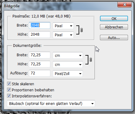
In the CryTiff window you take the preset for it, WAIT for the preview window and click "Bilinear".
PICTURE
Now, at last, you repeat this with your DIFFUSEMAP but WITHOUT RESIZING it! You grab your texture, save without alphachannel in the preset "diffusemap_highQ" and have done all textures ready for CryEngine.
PICTURE
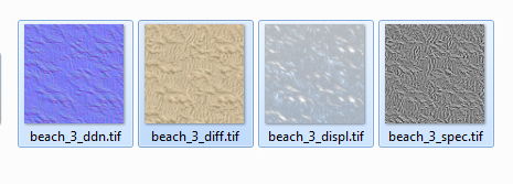
Copy now this 4 textures into the Hearts Of Oak texturesroot:
HDD:/CryEngine/GameSDK/objects/heartsofoak/textures
As soon as you start the CryEngine, the rc.exe (ressource compiler) starts automaticly the compression from the CryTiff to the DDS file format! After the finished compiling you can archive your CryTiff textures in another root outside the CryEngine roots. Its not important if you use in your materialfile (MTL) for the material or modell the *.tif or *.dds file extension. The CryEngine reads a tif as dds too when the tif is missing (what it should be).
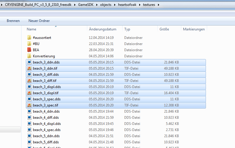
When you look close to the picture, you see the beach_3_ddn and beach_3_diff compiled and the beach_3_displ and beach_3_spec in progress (the file size is still ~11KB). The next thing you see is, that the normalmap was compressed in 4096x4096 down from ~49,2MB to ~21,8MB and the 4096x4096 diffusemap from ~same size down to ~11MB. The reason behind is the preset and compression of the textures, stored in the CryTiff.
The beach_4_displ.ddn and beach_4_spec.ddn below show you the same result, the beach_3 displ and spec will have after its compiling. In 2048x2048 the diplacementmap with alphachannel will be ~5,5MB and the 2048x2048 specularmap without alphachannel ~2,7MB.
PICTURE
Now we come to a special MTL setup for TERRAINTEXTURES. Other then modell-MTLs with its fast setups in the CryEngine Materialeditor, the Terraintextures need a good MTL-base to overlap / merge later ingame two textureborders at the ground surface without a noticeable border.
You can take this code as example and only change you texturenames. The settings for good merged overlap, is already set!
Code:
<Material MtlFlags="524288" Shader="Terrain.Layer" GenMask="208080200" StringGenMask="%BUMP_MAP%GLOSS_MAP%PARALLAX_OCCLUSION_MAPPING%TEMP_TERRAIN" SurfaceType="mat_soil" MatTemplate="" Diffuse="0.22713655,0.22713655,0.22713655" Specular="0.0090214908,0.0090214908,0.0090214908" Emissive="0,0,0" Shininess="10" Opacity="1" LayerAct="1">

<Textures>

  <Texture Map="Diffuse" File="objects/heartsofoak/textures/beach_3_diff.tif">

   <TexMod TileU="0.2" TileV="0.2"/>

  </Texture>

  <Texture Map="Specular" File="objects/heartsofoak/textures/beach_3_spec.dds"/>

  <Texture Map="Bumpmap" File="objects/heartsofoak/textures/beach_3_ddn.tif"/>

  <Texture Map="Heightmap" File="objects/heartsofoak/textures/beach_3_displ.tif"/>

</Textures>

<PublicParams BlendFalloff="0.5" DetailTextureStrength="1" PomDisplacement="0.0099999998" FresnelScale="1" FresnelBias="0.40000001" SelfShadowStrength="1.5" HeightBias="0.5" BlendFactor="2" IndirectColor="0.24680044,0.24680044,0.24680044"/>

</Material>
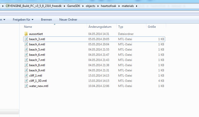
To hold later the terrainmaterialfiles separate from the modells, I placed them in the root:
HDD:/CryEngine/GameSDK/objects/heartsofoak/materials
You see, that I have setup a 3D- and watertexture too. The difference between terraintextures and modelltextures is for terraintextures, that you need to setup the material for each axis (X,Y,Z) when you want to paint it around terrainshapes, with more then one axis. This means rocks, cliffs, caves. Those textures I have named as prefix "_3D". I explain this later in the CryEngine materialeditor tutorial.
PICTURE
Inside the CryEngine Sandbox Editor, you can paint now the textures to the terrain and will get a good looking result. The textures overlaps good without any noticeable borders.
PICTURE
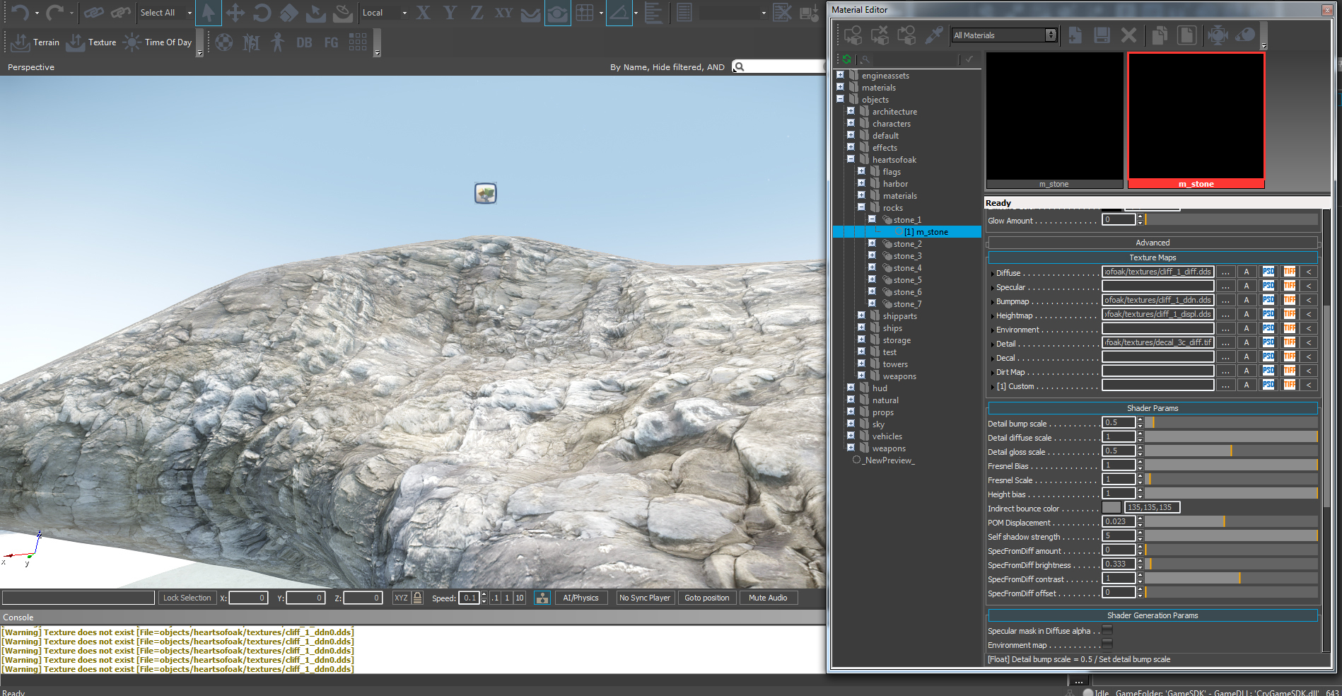
[3] CryEngine - Materialeditor
The most easy way to create a new material is to copy an existing *.MTL file from any comparable model. The advantage is to get a setup MTL, ready to load inside CryEngine.
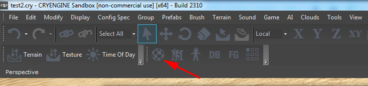
To start the CryEngine materialeditor, please open it from the tools bar, the red arrow points to
PICTURE
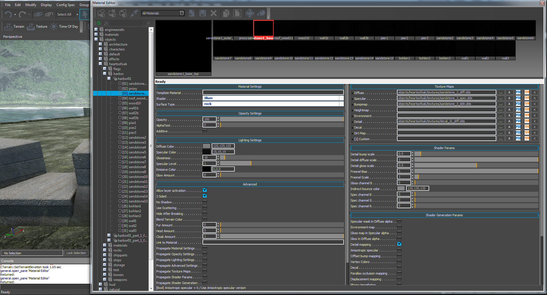
Once open, browse in the hieraryhe to the root where your MTL is placed in. In my first example I have load a simple material for the harbors sandstone surface.
Overview: At the left side you have your root of the GAMESDK structure, where you easy find below "objects" our heartsofoak" folder.
At the right side you see all setting you can change for your material. The right "settings" area is tiled in two sides. When reduced the material editors width, most only one column exist BUT ATTENTION: Then the "Advanced" options will blend off!
"SHADER": This setting defines what shader is used for rendering the material. Mostly "illum" will be used.
"SURFACE TYPE": Defines what surface your material is. This setting is responsible for the decals and particles when physical events hit the model.
"DIFFUSE- & SPECULARCOLOR": This option is not only useful for lighter or darker coloring of the texture. We use multitexturing by using sometimes the color for coloring a monochrom diffusetexture too. This means, that the same wooden planks texture can be breen and yellow. The specularcolor you can fit to the diffusecolor and its look ingame.
You can change it easy by click at the color. A colorchart comes up, where you can easy setup you color and brightness. You need not only to write in the RGB values. Try this out, what the best values for your model are.
"GLOSSINESS" means the reflection properties of your models surface. You need here to try the best value out. Mostly 1 - 10 is used.
"SPECULAR LEVEL": Means the level of your specularsettings. You need here to try the best value out too. Mostly 1 is used.
"EMISSIVE COLOR & GLOW AMOUNT": When a texture sends light then you need to setup here its color and glow.
"ADVANCED SETTINGS": In the advanced settings mostly only the first options are important for us.
- "ALLOW LAYER ACTIVATION": Ever set by standard
- "2 SIDED": An important option when you see a material from two sides. Normally you can only see the material in the direction of the normals form the model but sometimes you need both side (for example at sails)
At the right side of the settings window you see at first the TEXTURE MAP CHANNELS. Here is the place where you you write in the path to your textures.
At the first picture you see a simple DIFFUSE-, SPECULAR-, NORMALMAP setup but plus a dirtmap, placed in the DETAILMAP slot. Normally the DETAILMAP slot is a second normalmap. Sometime a second normalmap can give a surface an individual look (in case of dirt or scratches etc.).
But, an nice other feature is, that we can use this slot and its SETTINGS for good looking dirt textures too. You need only to place in the texture in the DETAILMAP slot an click in the SHADER GENERATION PARAMS at "DETAIL MAPPING". Now you have the new options SHADER PARAMS above it.
Play around and find out what look is great.
PICTURE
PICTURE of another (comparable) submodel- materialsetup
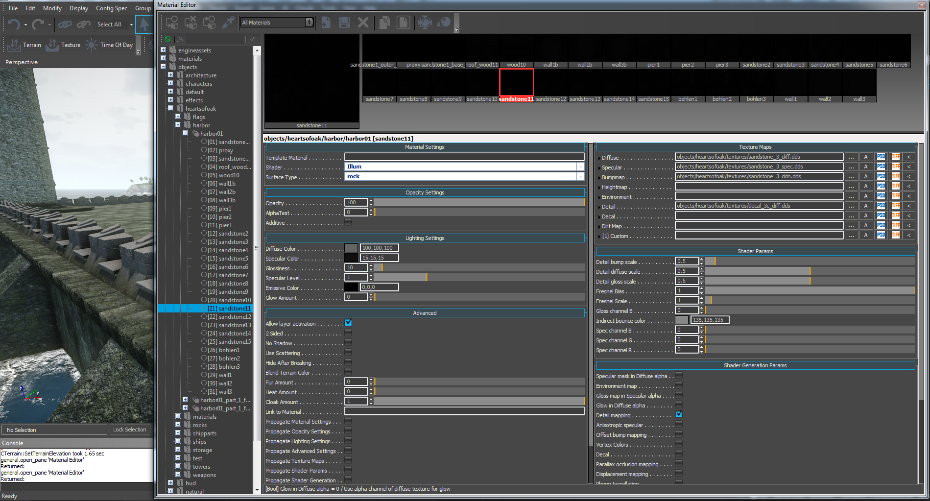
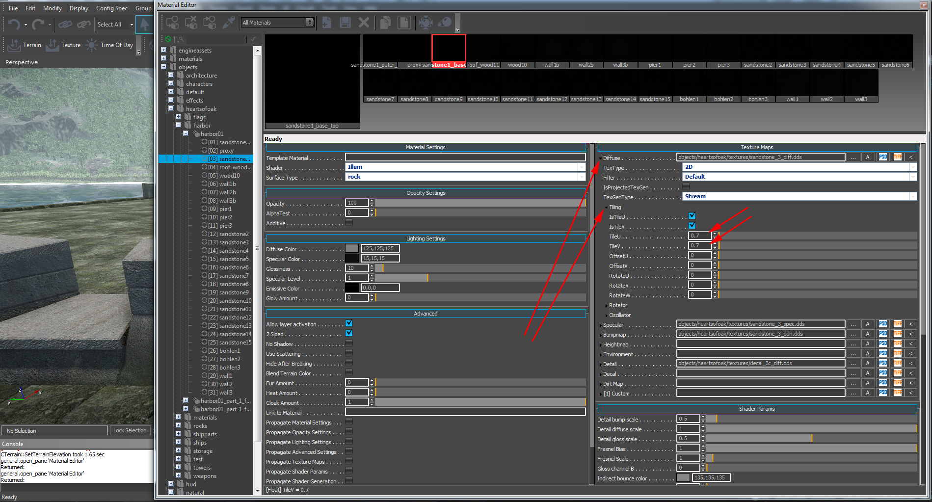
An greate advantage too is, that you can set independently to the other channels, the TILING of each layer. So you can setup for example a dirt layer tiled by 4x4 and the diffusechannel (with its AUTOMATICLY changing specular-, normal-, and heightmap) 1x1.
PICTURE
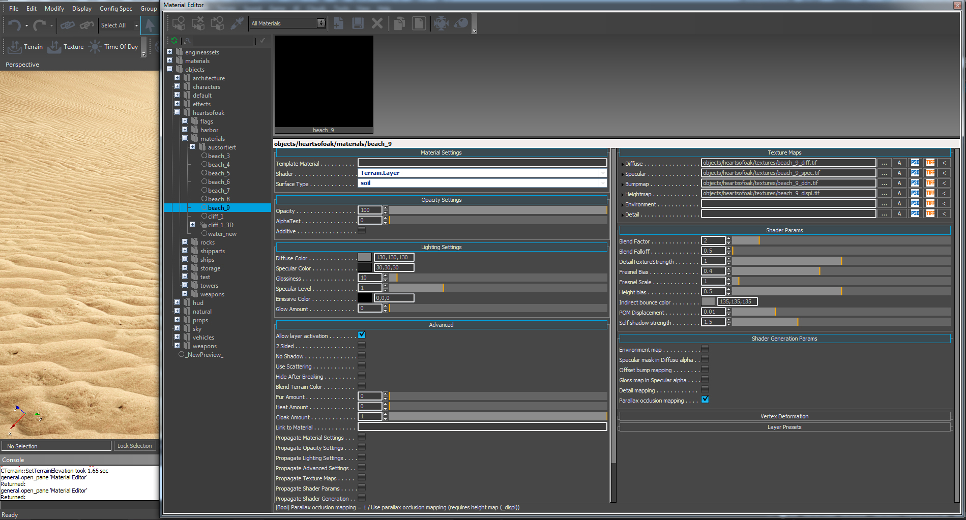
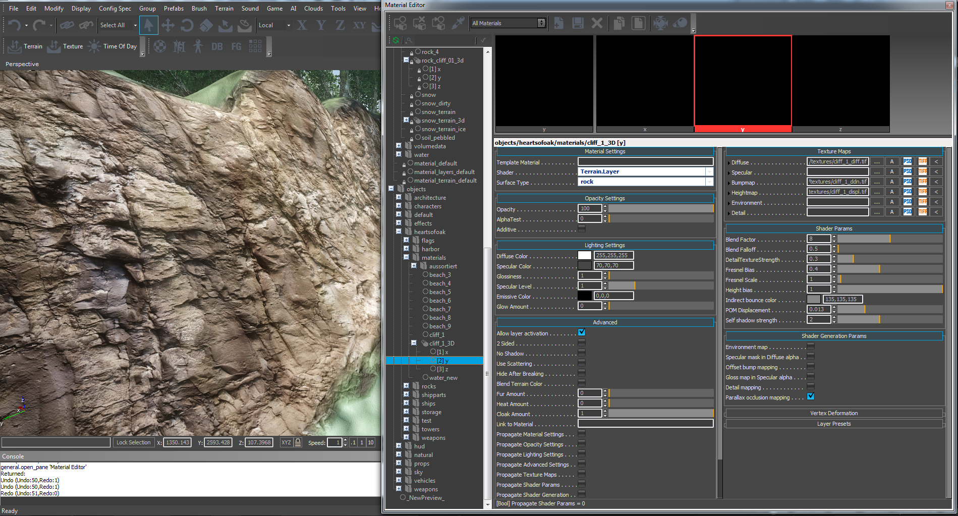
The next picture is an example for a Parallax Occlusion Mapping (POM) texture. The second example here is, that this material is setup not as "ILLUM", its setup as "TERRAIN.LAYER". Note this: Modeltextures mostly are vegetation or illum but materials you like to paint to the terrain, you need ever set as "TERRAIN.LAYER"! POM works independently in every channel.
At the right side of the settings you see the POM texture set into the HEIGHTMAP channel and the highlighted option in the SHADER GENERATION PARAMS. In the SHADER PARAMS settings above you can now setup POM DISPLACEMENT and SELF SHADOW STRANGE.
IMPORTANT: To get later a great overlapping / merged view, the first SHADER PARAMS like BLEND FACTOR and CLEND FALLOF etc. are need to setup wise. The example you see in the picture below are a good value and a should be a base for your material.
PICTURE
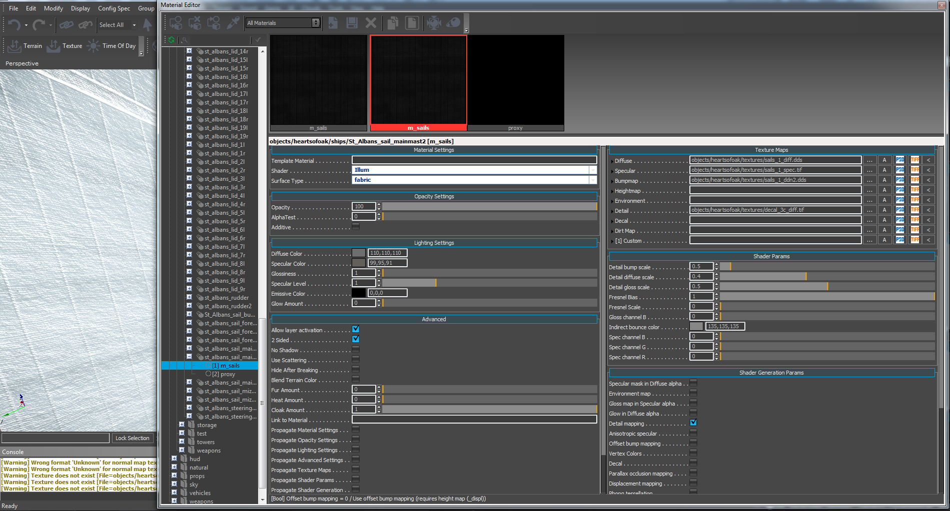
At the next picture you see a sailmaterial with a dirtlayer too. You know the most setup options from the examples above but please take a look at and....
PICTURE
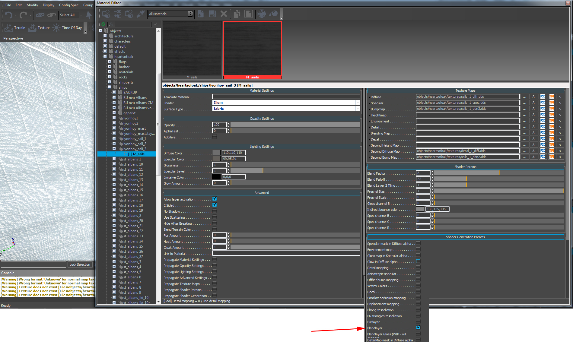
... compare it with the setup, you see in the next picture. In the example below you see the dirtlayer not placed in the DETAILMAP slot, you see it placed as second texture in the CHANNEL when highlighted the option "BLENDLAYER". A blendlayer have other option then the detailmaplayer. The blend texture can be fracturised of drawn with a fall of. You can test around what you like more or what options you need more. The BLENDLAYER texture are very good placed as using at mossy rocks etc.. There, the blendfactors works better as in detailmap slots. It depends what "look" you will get. Please try this out at you model.
PICTURE
Here the next special is coming. Multi-axis terrainpainting need in contrast to the beach material example a setup for each painting axis in one material. This means mostly materials for rocks, cliffs, caves etc. = material for map areas where you overlap the painting axis.
When open a multi-axis material, you see the materialnode and inside CASE SENSITVE written the submaterial setups. Every submaterialsetup looks like a own material. Thats right, it IS one material as submaterial in the materialnode. Each axis will separate painted but fit togehter by the channel, based on the material axis naming.
PICTURE

Here you see two axis setups and you see all are the same. When you setup a material like this, please paint one flat axis you see in the map, setup the material and copy the settings to the other channels.
PICTURE
PICTURE
PICTURE
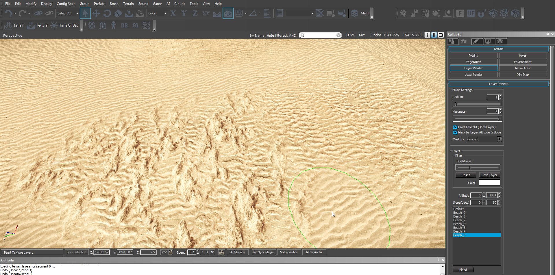
[4.] Setup of terraintextures in CryEngine "Terrain Texture Layer Setup"
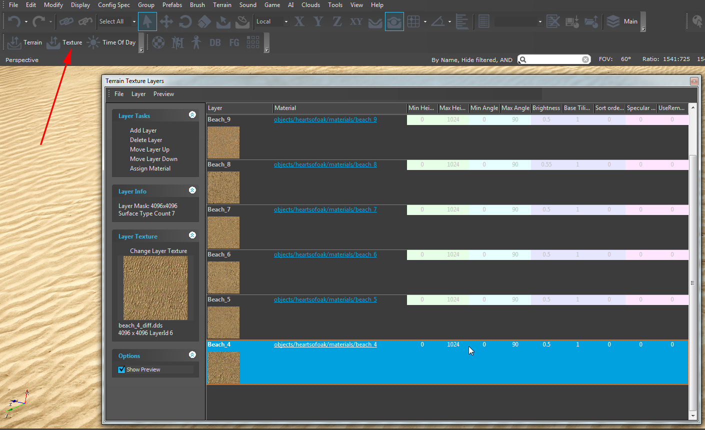
When you like to setup a new texture for terrainpainting, you need at first the TERRAIN TEXTURE LAYERS dialog. In the picture below you see the last setup layer is "Beach_4". To complete my "beach_3" example, we will learn in this section how to setup a new layer for this texture.
PICTURE
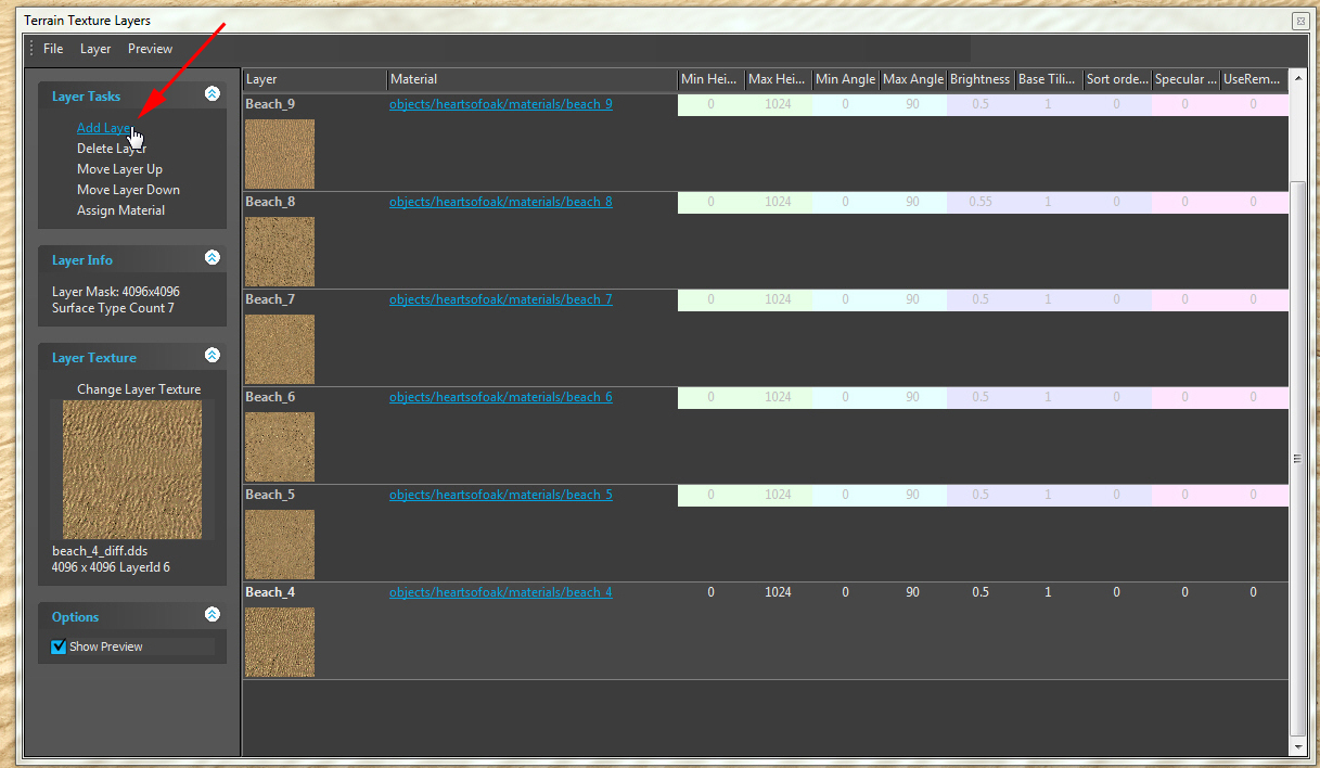
Click on "ADD LAYER"
PICTURE
You see now a "NewLayer" with the assigned material "Materials/material_terrain_default". This, we need to change to our own material and click direct on the material-link, the red arrow points to.
PICTURE

Have you done this, the CryEngine materialeditor comes up. Browse here to our
objects/heartsofoak/materials
root and highlight the material you want to assign to the layer
PICTURE
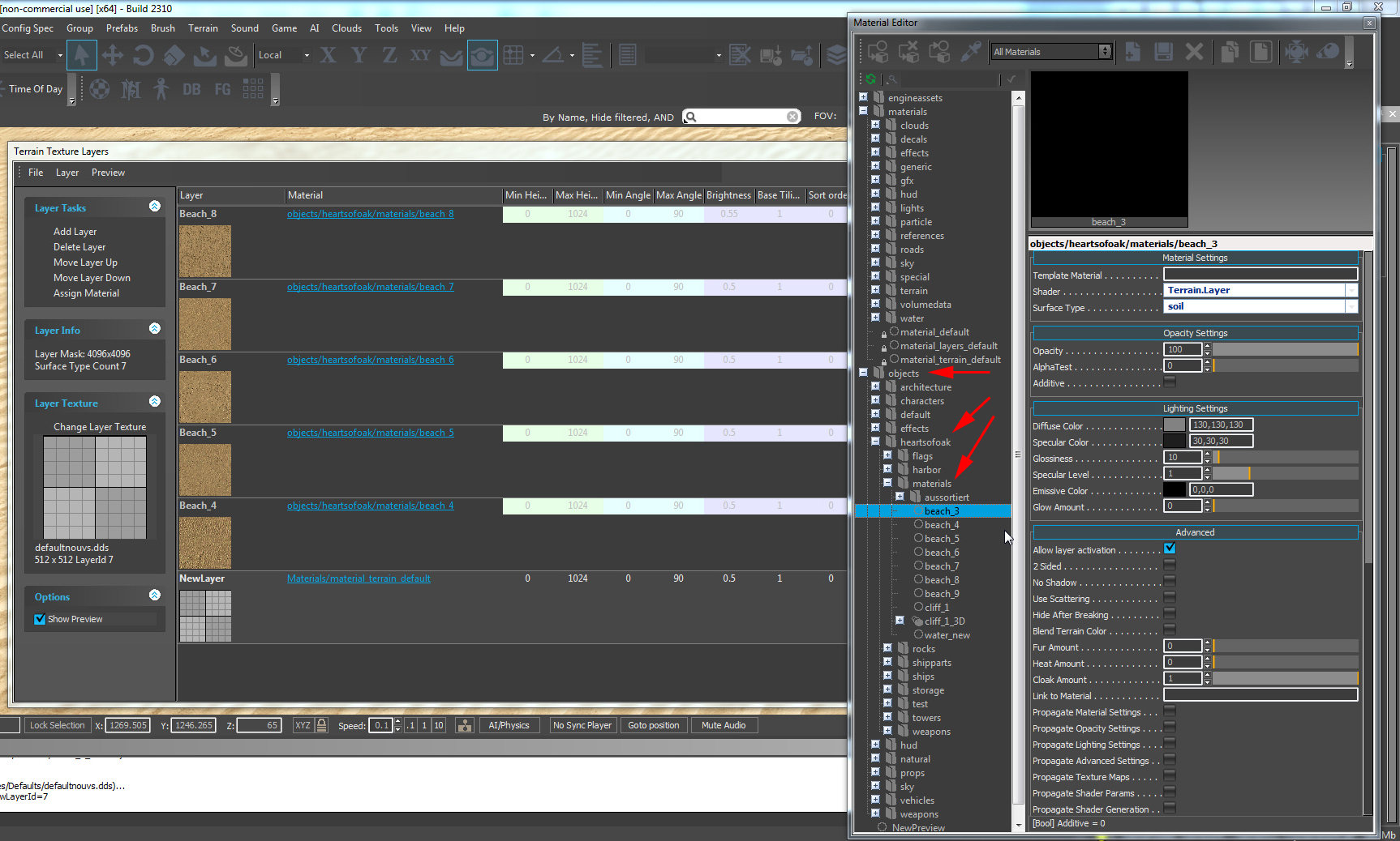
To assign the material with success, you must highlight it in the CryEngine materialeditor and click in the terrain texture layers window at "Assign Material". Have you done this, the materialpath is changed in our new layer.
PICTURE
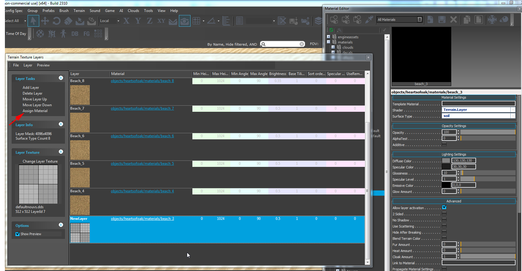
Make now an doubleclick at the layer name and change it to a name you easy understand later in the layer painters setup.
PICTURE
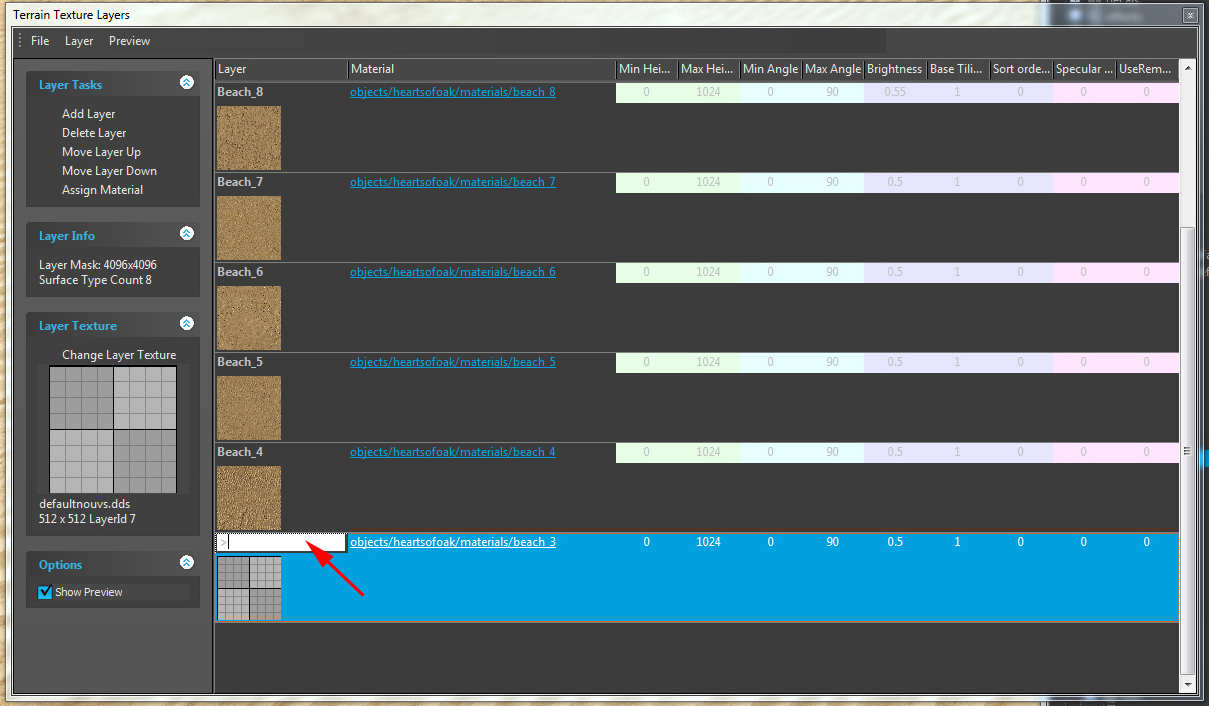
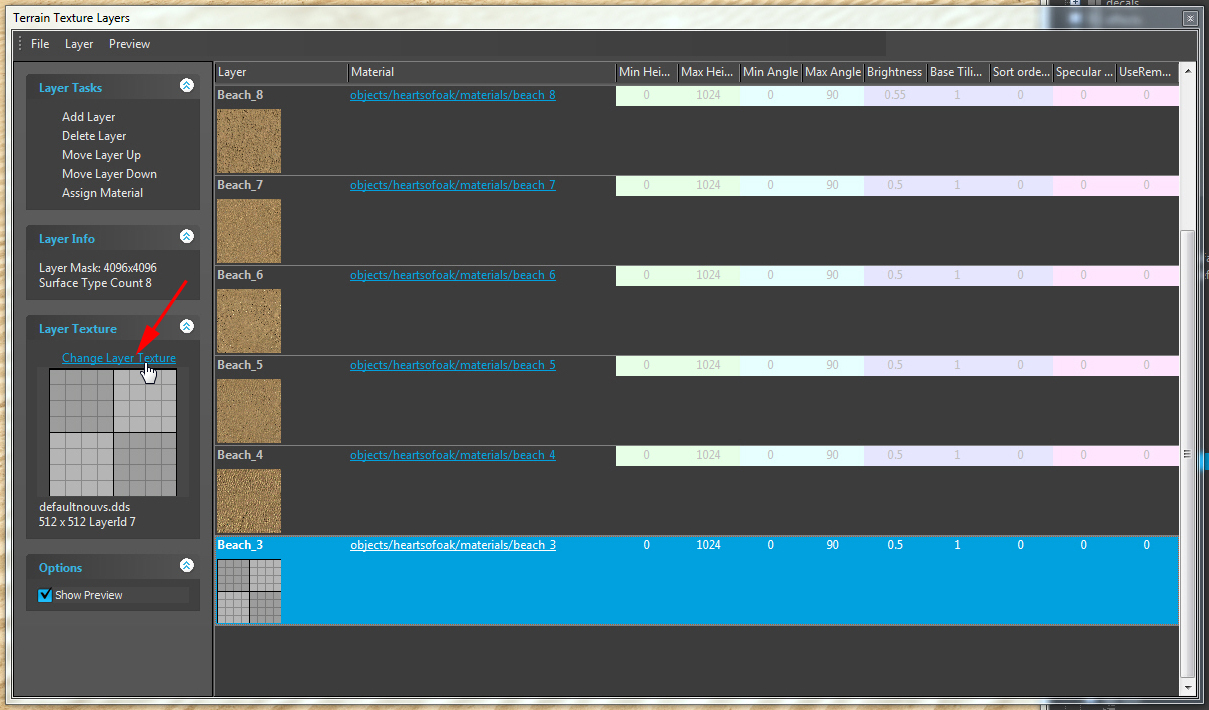
In the next step we want to change the layer mask. Its named strange here because you material already set in the path. You can set a special mask to the layer itself but we need the original texture and click at "Change Layer Texture".
PICTURE
Change here the standardroot of the default mask texture to our own texture (the same like we used in the naterial)
PICTURE
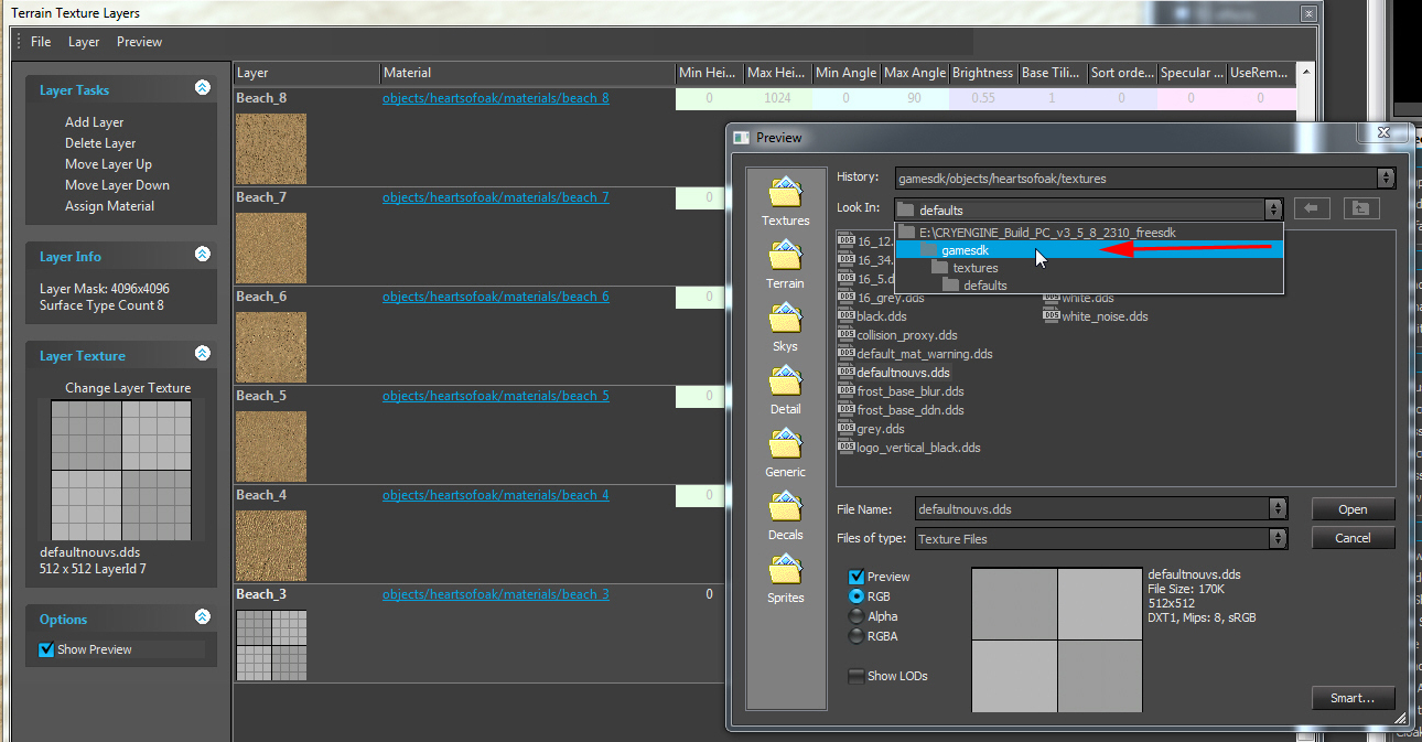
PICTURE
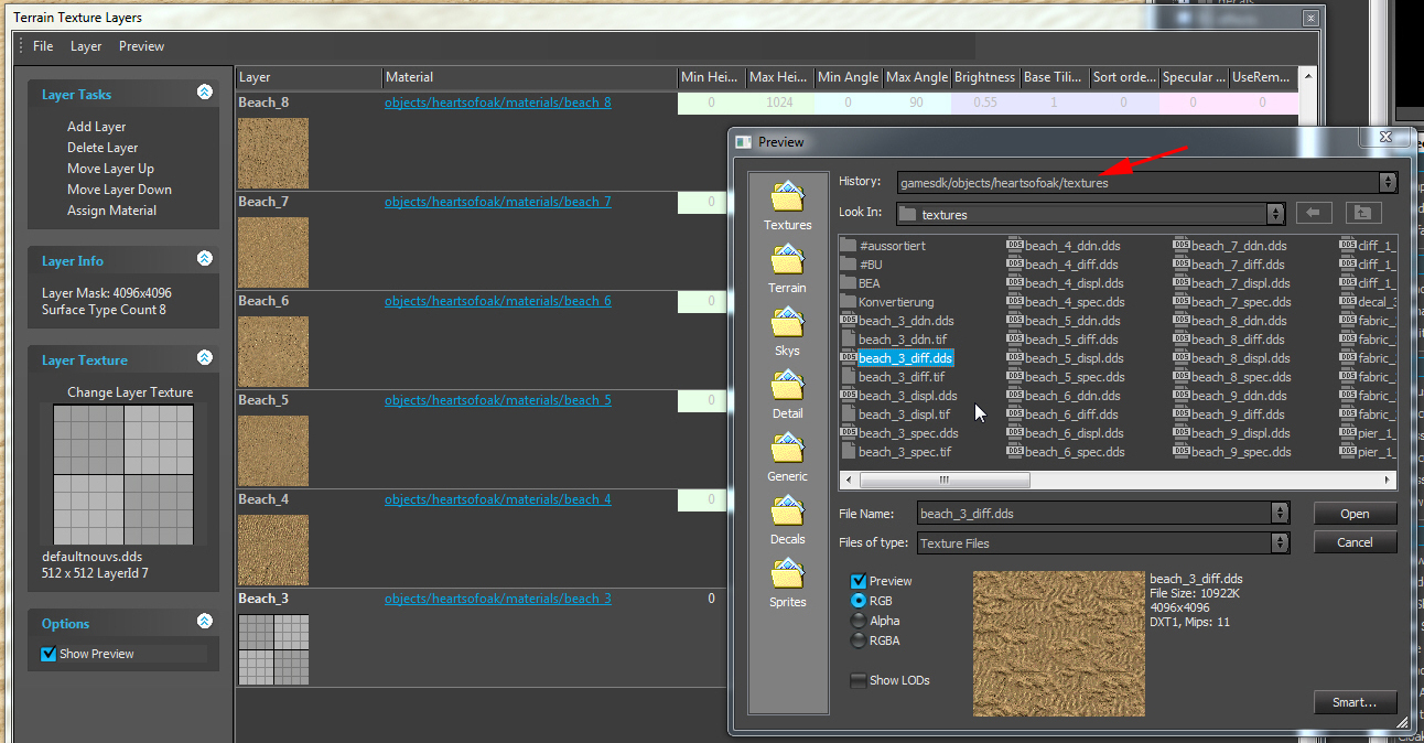
After clicking "Open", the mask should be changed.
PICTURE
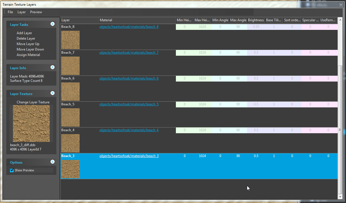
Short additional Info the all the vaules in the right area of this "terrain texture layers" window: You can change this values later in the layer painter dialog too. Only the brightness you should test and setup here because the color chart setup later is independent to the more easy brightness here, hard.
Painted to the terrain, our new texture looks great:
PICTURE
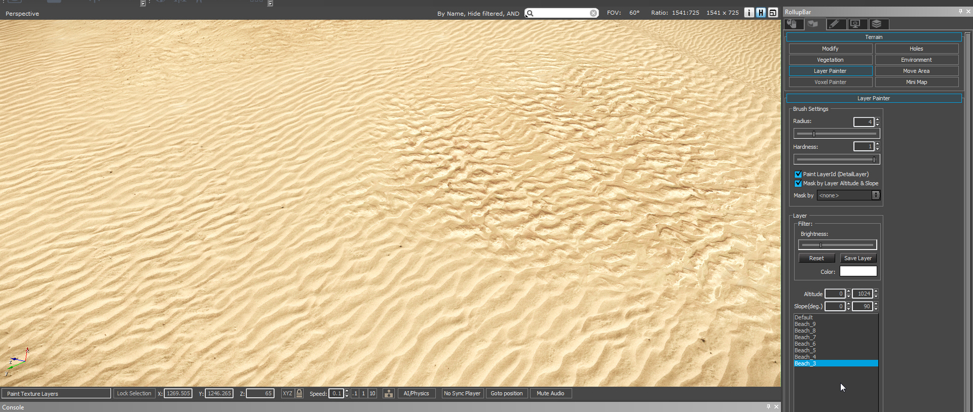
PICTURE
// rd
-
