
-
Visit our website www.piratehorizons.com to quickly find download links for the newest versions of our New Horizons mods Beyond New Horizons and Maelstrom New Horizons!-
Join our discord server for regular podcasts/AMA about upcoming and released pirate games (Caribbean Legend, Corsairs Legacy, Ahoy, ERAS 2, etc.):

-
Quick links for Beyond New Horizons
- Download latest version
- Wiki - FAQ - Report bugs here - Bug Tracker on Github -

Quick links for Maelstrom
- Download the latest version of Maelstrom
- Download the latest version of ERAS II - Download the latest version of New Horizons on Maelstrom
-
Join PiratesAhoy! on our social channels:


-

Quick links for PotC: New Horizons
- Download latest version
- Wiki - FAQ - Report bugs here
-

Thanks to YOUR votes, GOG.com now sells:
- Sea Dogs - Sea Dogs: Caribbean Tales
- Sea Dogs: City of Abandoned Ships
Vote now to add Pirates of the Caribbean to the list! -
Quick links for AoP2: Gentlemen of Fortune 2
- Downloads and info
- ModDB Profile
- Forums Archive -

A Pirate Podcast with Interviews
Music, Comedy and all things Pirate!
- Episode Guide - About - Subscribe -
- Twitter - Facebook - iTunes - Android -
- Youtube - Fill the Coffers -
(3b) CryEngine - CGA setup Maya
- Views Views: 565
- Last updated Last updated:
-
This tutorial will be updated regularly! (03. April 2014)
In contrast to the static geometry format CGF, have the mesh - animated format "CGA" a few differences, where we need to look at.
CGA is an animated mesh. That means NO character-bone-system (this is CHR-format). CGA files contains keyframed simple actions like rotation, movement etc..
The CGA format is need as base for vehicles although for example a hull of an ship is not animated. The reason is the system of physicengine calculation inside the CryEngine, where CGA is other way handled as CGF.
For CGA we have two options we can choice:
1.) When you take for example an simple animation (like an rotation for a windmill), you set the pivot point to the center of the rotation axis. In 99,9% of all cases is this in Maya or Max the 0,0,0 at the X,Y,Z values at base coordinate-raster of the grid. This wind-wheel can be setup with a simple rotation and export as CGA.
An CGA can ever handle only one mesh with LODs, so all additional meshes to the animation mesh need to be attached. In the case of the windmill is this for example the wooden- and fabric part of the modell. The wooden part is what we export as rotation keyframed CGA. That we can attach the fabric part to the CGA, we give the CGA an attachment node, with the same keyframe animation as the wooden wind wheel group. The fabric part we export as CGF and attach to the CGAs helper. In result both parts are rotation. The wind wheel part with fabric attachment we attach to the windmill itself, with the same way.
IMPORTANT: Mesh can never be keyframed work in CryEngine! You ever need to keyframe the helpernode or the GROUP where the mesh is inside!
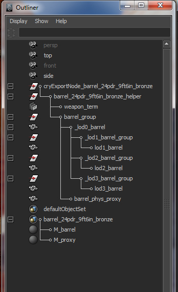
Here is the hierarchy of an working CGA:
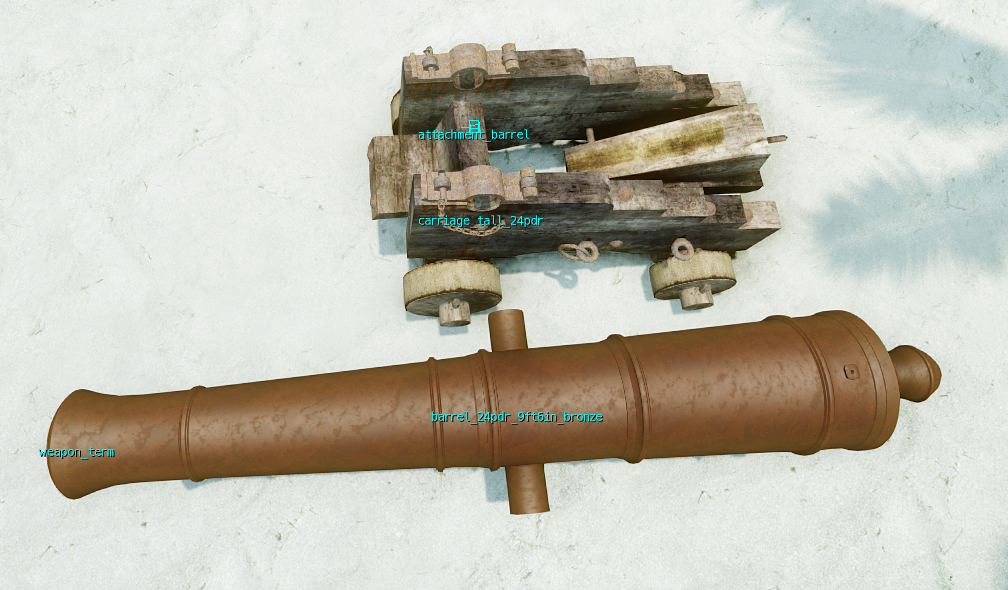
The proxy I left in my example but you can attach the same way like in the CGF, direct in the "MESH_GROUP" parallel to "BARREL_RENDER" mesh. Direct in the "CANNON_24PDR_9FT_6IN_BRONZE_TALL_HELPER" group you see the "WEAPON_TERM" helpernode. Named in "ATTACHMENT_XYZ" let the engine read this as attachment helper.
2.) In case you need no readable helpers by the engine and like to export an CGA that works with more then one LOD-set you need to do without the chance to ever can attach useable helpers into this group.
You need to use an hierarchy like this:
>>>>>>>>>>>>>>>>>>>>>>>>>>>>PART 2<<<<<<<<<<<<<<<<<<<<<<<<<<
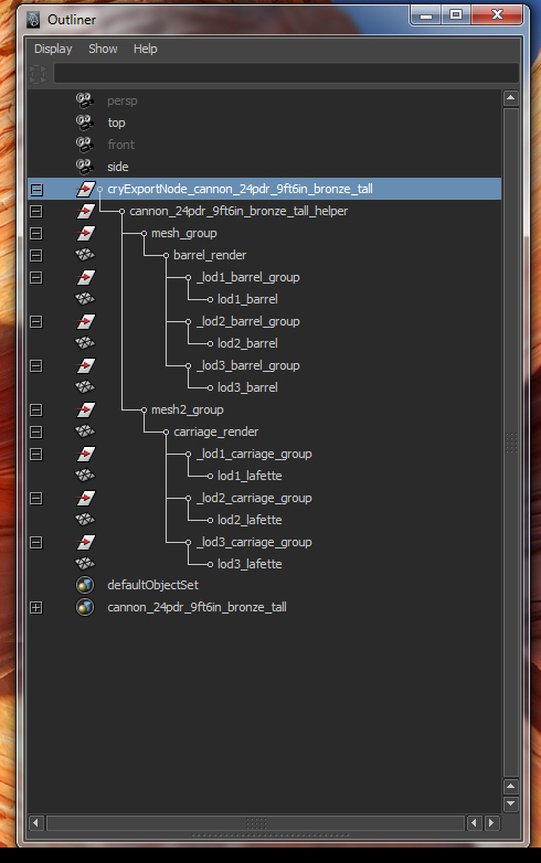
Example for LOD using. An proxy for an modell can contain the whole mesh of all parts and can be sort in the root of any part of an modell.
Example of an cannonproxy. Modell (identical with proxy) = Cannon (part) + Carriage (part)
Important: That animated CGA will work inside the SDK animated, the CGA need the additional file "ANM" that stores the animation itself. ANM-Files (Animationfiles) for CGA-files (Crytek animated geometry (exportformat)) EVER ONLY animate GROUPS and HELPERNODES. NEVER the Geometry direct (inside Maya or Max)! Key ever the Groups and the helpernodes!
Picture of the Hierarchy and the animation manager from CryEngine Exporttool Maya:
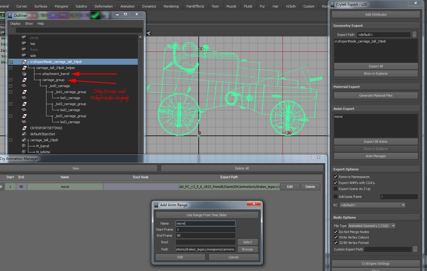
2 pictures Cannonsetup when you use the way I post in point 1.). You see two parts with lods and the carriage with attachment helper:
The hierarchy of this both files:
>>>>>>>>>>>>>>>>>>>>>>>>>>>>>>>>>>>>>>>>>>>>>>>>>>>>>>>>>>>>><<<
SPECIAL CGA - ANM setup:
Hey Guys,
Sometimes you need a more special setup when animating geometry, and for this it’s important to know a little bit about the technique behind Maya, to ensure your model fits the CryEngine export requirements.
The following example looks simple but it isn’t. Maya users should know what I mean.
When you want to rotate an object in a very complicated orientation and position, like a gunport lid, you need to decide how you can set its proper rotation and export. Remember, you can only key groups and CryEngine helper nodes. The job is clearly to orient the pivot point of the lid’s group by zeroing the transformation values to the lid’s orientation.
Let’s take a look at the example "lid" itself:
A lid’s position on a ship’s hull is never parallel to any axis. You always have an angle in every direction, so you will need to have two points to properly orient the lid. In Maya and for CryEngine export, you need one special pivot group setup for this. Before I tell you how this works, I will show you some methods to avoid (false methods). Believe me, most other workarounds are too complicated, waste time before the result works, or just won’t work at all. Remember, what works in Maya may not work when exported.
Here is an overview of the methods and most of the problems behind them.
Basics 1: Every part has only one pivot. The same applies for groups and helper nodes. When you only want to rotate the lid up and down, this always results in movement across all three axes when you placed the pivot of the group to one lid’s edge and zeroed it. Why? Remember that the lid is never parallel to any axis, and when you try the normal way to freeze the pivot’s transformations, you have a predefined value in its transformation values when the group is set back to the right lid’s position. What this means is, there is no simple way to rotate the lids up and down. You need to use a workaround for the best results!
Basics 2: I found something out in my research process of the lid rotation technique: When you take a look in this Wiki part 1 above, you always see a main group called “CRYEXPORTNODE”. Only this group must be placed in the centre of the coordinate axis 0,0,0 (rotation, scale and position at all axis 0,0,0). All other parts and groups can be placed where you need them.
Common model hierarchy: Top node (called “parts group”) contains the parts (sub-models) of your model. Remember:
Model = Lid
Sub-models = Wood interior, Wood exterior, Metal parts and Rope
(In this example a lid has four materials, and you must set up a sub-model for every material (remember this from other setups).)
PICTURE of a standard setup for the lid:
Remember, to get ANMs of CGAs working, you can only key the groups and helper nodes! This knowledge is available on the Wiki already.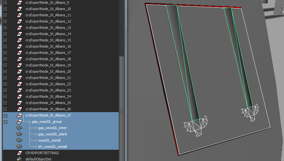
FALSE METHOD 1: (Example for informational purposes only; do not use!)
Based on what you know from “Basics 2” above, at first you might think to use what Maya or similar 3D programs can do now. When you move the pivot of the parts group to the edge that should be fixed when rotating, you will see first, when using the rotation tool, that the lid loses the position of the other side. The next logical step is to align the rotation axis to the model axis.
For this workaround, normally you have the following checklist:
1.1. Set up the parts group pivot to one edge of the lid and freeze its transformations.
1.2. Align the lid so that it’s parallel to all axes (a huge task for every lid...) step by step. This means aligning the X axis, noting the value and freezing the transformation, then repeating for Y and Z. The freeze after every axis alignment ensures only one rotation axis in the next step. Remember, that the lid is placed in all 3 axes, and whenever an axis has a predefined value, the other changes with the next rotation. So you need to freeze after every axis alignment.
1.3. With the values you noted in point 1.2, you bring the group back to the orientation where the lid fits the original position.
What you have now is a group pivot that fits to the lid but its values are predefined! Problem! When you now freeze the group’s transformation, the pivot’s orientation jumps back to world alignment. But let’s try the groups job with the predefined values and see what happens:
When you rotate the axis of the parts group up and down, all looks good because the second lid side seems to fit the rotation axis...
BUT: What is now working in Maya’s viewport is changing the result when you key the group. For example: (Remember: GROUP rotating) Set key 1 at frame 1, in the closed position of the lid. Move the time slider to, for example, frame 90 and set the keys for the open position. When you rotate the group by hand with the manipulator’s axis, all seems fine, and when you have set the keys you think it’s OK, but it isn’t.
When you now play the animation, only the first and last frame fits. In the time the animation is running, the second side of the lid never fits its position and wobbles around. The reason is that the key animation curve is running LINEAR through the 3D space from frame 1 to 90, and takes its orientation base as the predefined orientation of the group. This displaces the other side of the lid. To solve this in this method here, you must set every frame from 1 to 90 by hand, and for every frame in all 3 rotational axes! Do you want this to do for a 74 gunner? I think not.
So please beware of this method but learn from it!
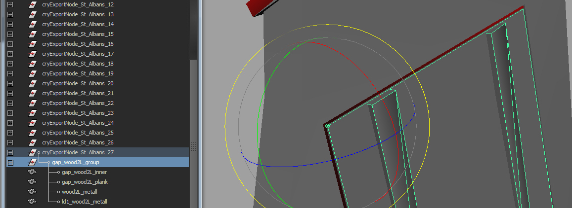
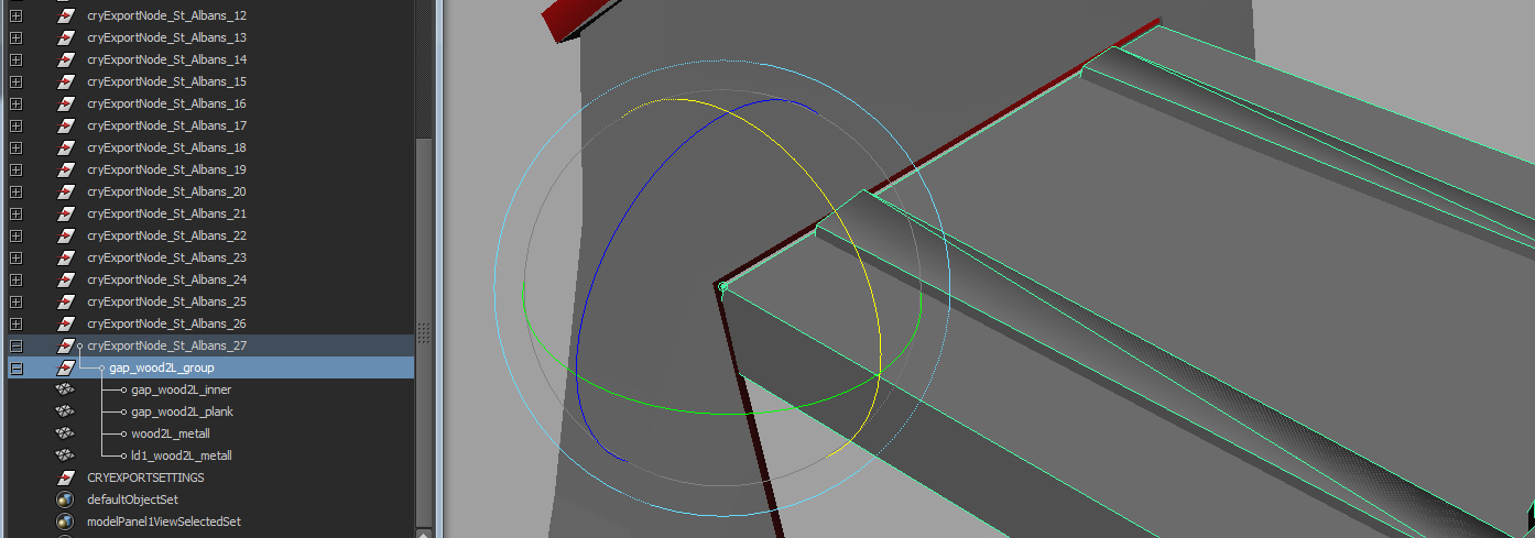
PICTURE of axis orientation:
You see in this picture the set position of the group’s pivot and its orientation in the 3D space. You see all axis (X,Y,Z - green, blue, red) fits to the lid’s orientation (the yellow manipulator is the global one that moves along all axes when use).
PICTURE of moving the lid up by hand:
Here you see that it looks like it works, but it doesn’t when set in keyframed animation!
PICTURE of the result when the animation is keyframed. The other side of the lid doesn’t fit its position between the set frames. It wobbles all around! I have copied the group for this screenshot, so you can see the result better.
FALSE METHOD 2: (Example for informational purposes only; do not use!)
OK, so when Method 1 fails, your next idea might be to centre the group node’s pivot to the top axis of the lid. As above though, this won’t work!
FALSE METHOD 3: (Example for informational purposes only; do not use!)
After failing with group animation, you might try to use a rig and bind them to the parts. Here is where you leave parts animation and enter character animation. For this, you bind and paint all parts and animate it. This is easy because a bone (two joints) always fits its subordinate parts. It looks like you have the solution but this is, unfortunately, not the right one! The attachment of a CHR (Character file) with its CAF animation and a definition in CHRPARAMS to a ship is an unbelievable amount of work (that we try to bypass for sails too) and requires a lot of entity setup in the Mannequin editor. This solution is too awkward and may not work in later SDK- and Mannequin editor updates. Believe me: you must set up many lids!
In contrast to the CGA-ANM parts animation, a CHR with CAF mesh animation always stores the position of each mesh vertex. That’s the reason why characters are deformable (walking, running etc.). The method is useable, but as I said, much too awkward.
CORRECT METHOD:
Last but not least, the working method... It’s a crazy mix of both systems, but we only use deeper knowledge of axis and joint orientation to get our result!
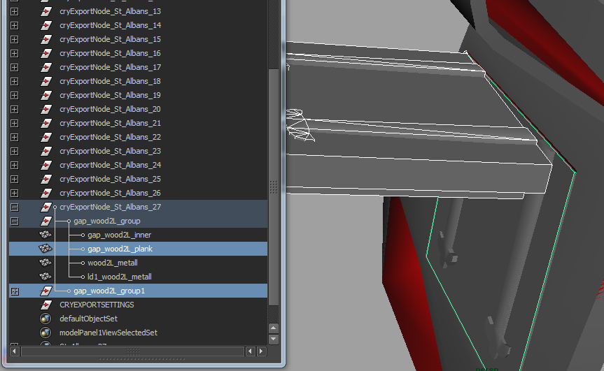
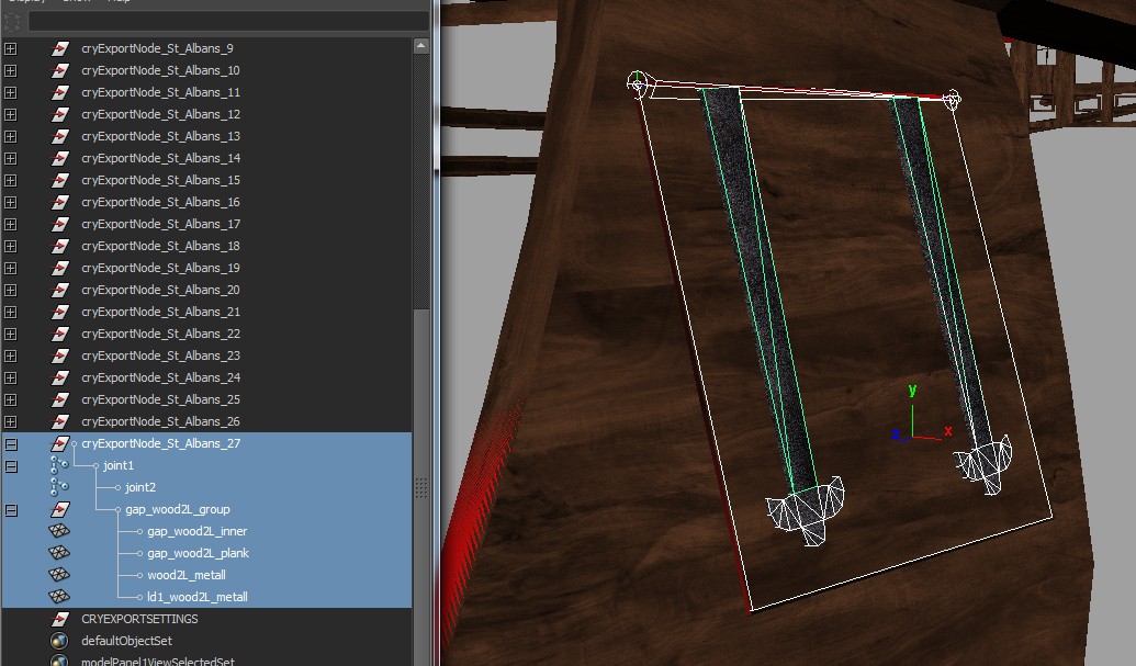
Inside the CRYEXPORTNODE, you place a bone (two joints) and place the lid group under the first joint (see picture below).
Technique:
In a rig, a joint automatically sets its "joint orient" when placing a second joint at another position. Here we use the rotation side of the lid. To set the joint’s orientation, place them by using "snap to vertex” (V).
The interesting thing (and for us, the important thing) is that the joint below the previous joint always has zeroed joint orientation (0,0,0..) at all axes in position, location, rotation and scale, ALTHOGH its axis (pivot) is oriented to the previous joint!
Here comes the secret: Combine this knowledge with the other knowledge available on the Wiki! I have said that freezing the transformations of the group axes and moving them to the lid’s real position results in a failed animation, but moving the axes was correct. The reason behind this is that the axes, to bring the lid back to its real position, always end in predefined axis rotation values.
When you now combine both facts, then it is the key to give the child group of joint 1 the same inherit properties like the joint itself but with zeroed transformations (WHAT WE NEED). In the tools option you find this option (inherits transformation) and when set, voila, the group gets, with ALL zeroed properties at all axes, the orientation of joint 1.
What looks like the second fixed point now is normally the reason of the joint’s orientation, but in reality, the second joint defines the axis direction of the first joint and that results in joint 1 orientation to all axis of the lid when placed along the rotation side. In this case the joint inherits its properties with zeroed values to the group.
My next test confirmed this. IMPORTANT: When setting up the bone and placing it in the group, you might delete it immediately afterwards because the axis in the group is already set, BUT (IMPORTANT) the group inherits the position in 3D space from joint 1 too, and this results into the jump of the group to position 0,0,0. So, you MUST leave the bones inside the hierarchy in the Cryexportnode, to save its inherited position values from joint 1!
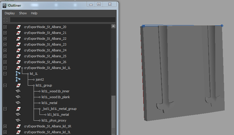
PICTURE of working setup (without Proxy and LOD):
In the viewport you see the bone, and the right hierarchy in the outliner (the highlighted one).
PICTURE of testing possibility in character editor in CE:
Use File > OPEN and open your CGA. The ANM loads automatically. Now chose your animation in the "Animation" window on the right side.
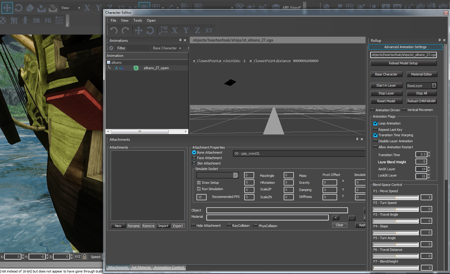
PICTURE of testing possibility when linking to the ship as ENTITY ANIMOBJECT (setup see picture). Please ignore the incorrect UVs on the lid’s sides. This is what I mean with fast setup test ships.")
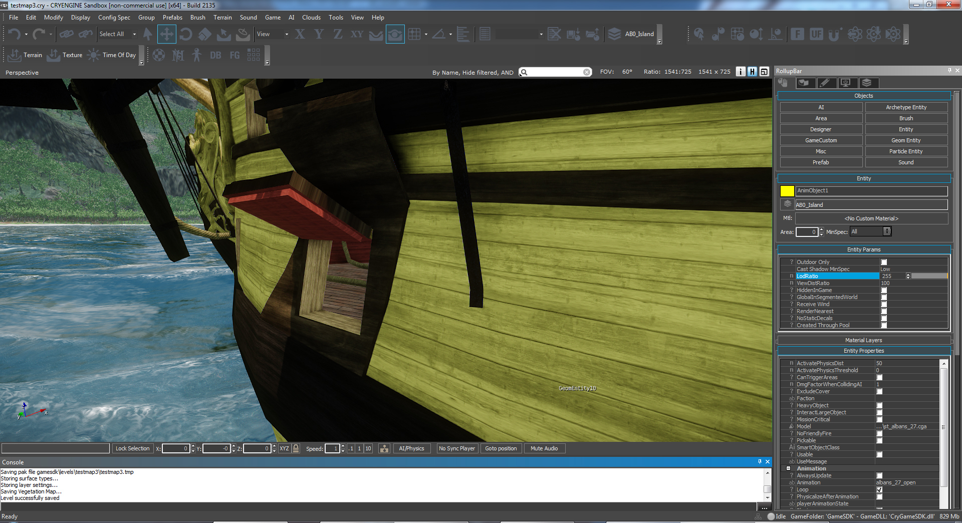
Please export every lid as separate modell. There are a few errors when you export all lids in one modell. After animating the lids, you need only to sort it into an own CryExportnode and export separately.
PICTURE: Here the final hierarchy, with LOD, proxy and an example of possible setup of LEFT HAND and RIGHT HAND placed LIDs in outliner:
Edited for improved readability by Armada.
-
