
-

Visit our website www.piratehorizons.com to quickly find download links for the newest versions of our New Horizons mods Beyond New Horizons and Maelstrom New Horizons!-
Join our discord server for regular podcasts/AMA about upcoming and released pirate games (Caribbean Legend, Corsairs Legacy, Ahoy, ERAS 2, etc.):

-

Quick links for Beyond New Horizons
- Download latest version
- Wiki - FAQ - Report bugs here - Bug Tracker on Github -

Quick links for Maelstrom
- Download the latest version of Maelstrom
- Download the latest version of ERAS II - Download the latest version of New Horizons on Maelstrom
-
Join PiratesAhoy! on our social channels:


-

Quick links for PotC: New Horizons
- Download latest version
- Wiki - FAQ - Report bugs here
-

Thanks to YOUR votes, GOG.com now sells:
- Sea Dogs - Sea Dogs: Caribbean Tales
- Sea Dogs: City of Abandoned Ships
Vote now to add Pirates of the Caribbean to the list! -

Quick links for AoP2: Gentlemen of Fortune 2
- Downloads and info
- ModDB Profile
- Forums Archive -

A Pirate Podcast with Interviews
Music, Comedy and all things Pirate!
- Episode Guide - About - Subscribe -
- Twitter - Facebook - iTunes - Android -
- Youtube - Fill the Coffers -
MAYA - Creating a ships hull using "loft-extrude"
- Views Views: 1,532
- Last updated Last updated:
-
This tutorial will be updated regularly! (21. Feb 2014)
The sampleasset for this tutorial you find here: Click Me
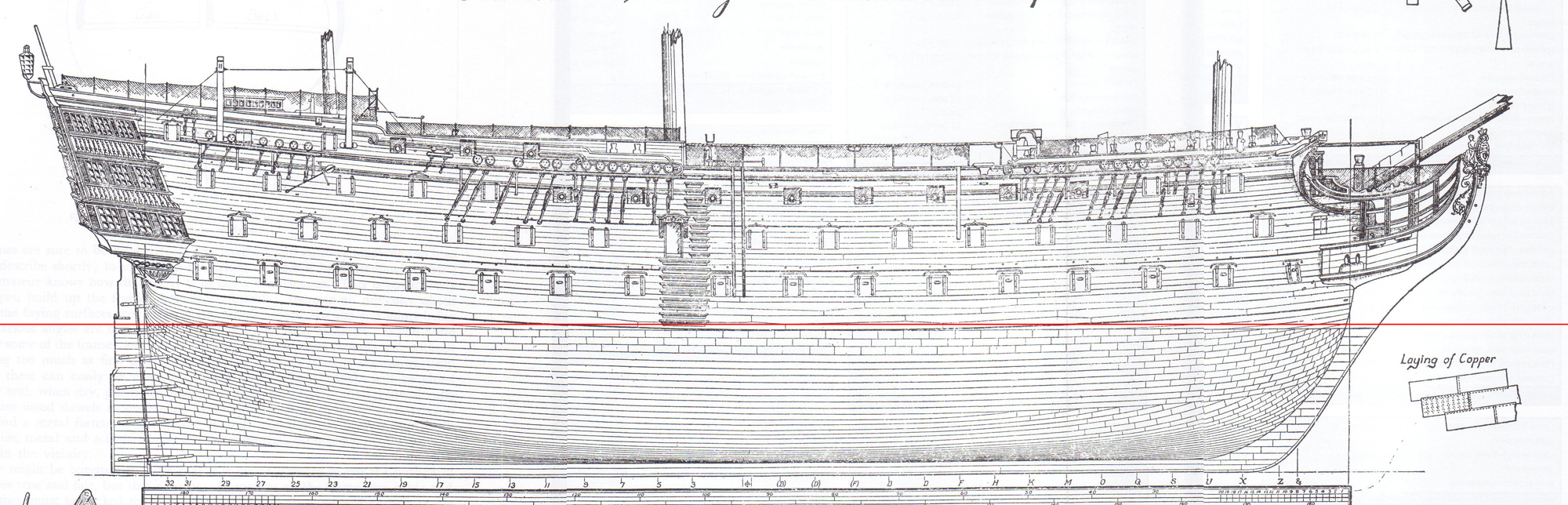
Requirement for creating a ships hull is, that you have the original shape plans (drawings) from front, side and top view and have setup these in the same scale to each other.
I mean drawings like this:
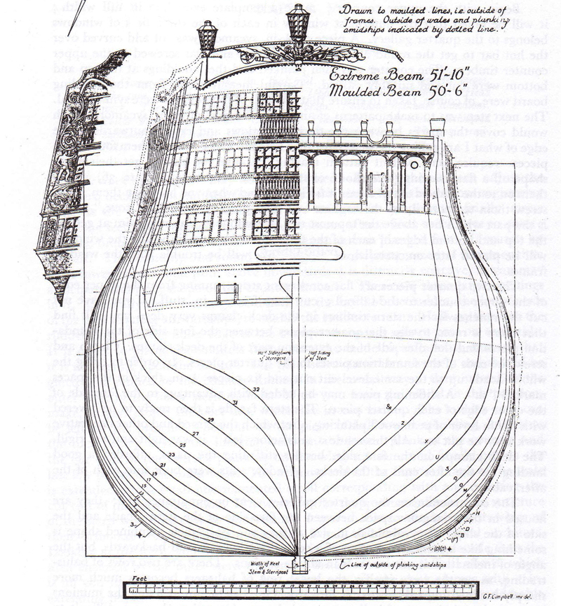
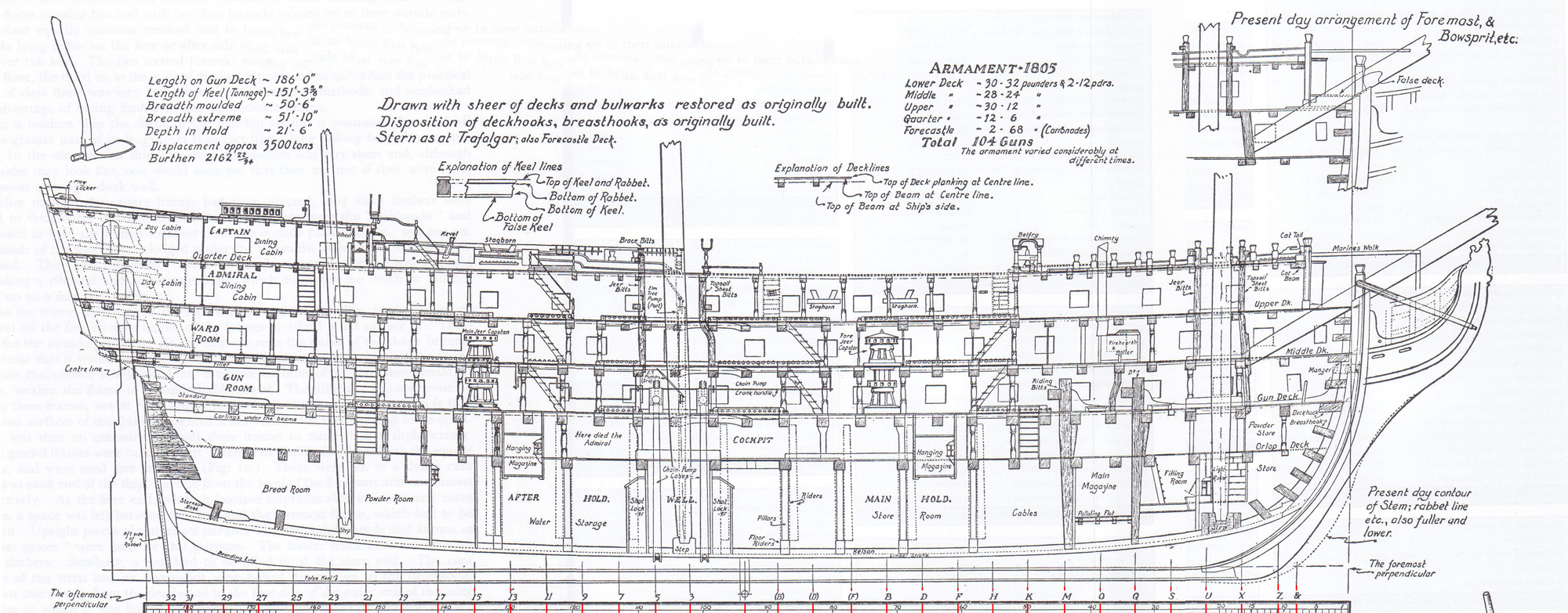
If you have scaled and straighten the drawings (use best an own scale in tools like "photoshop"), then setup the plans as imageplanes in Maya, in every view (top, side, front (or back)).
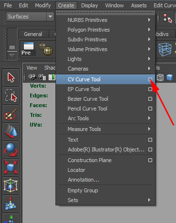
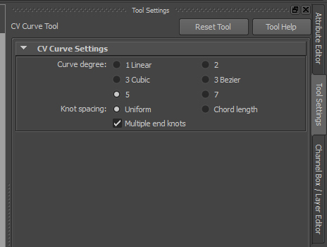
Create now, based on the drawing "front", the first CV curve. Start the tool with click on the "OPTION BOX" (the small quad, the red arrow is point too).
PICTURE:
Set the follow settings:
PICTURE:
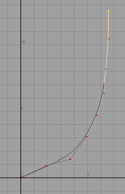
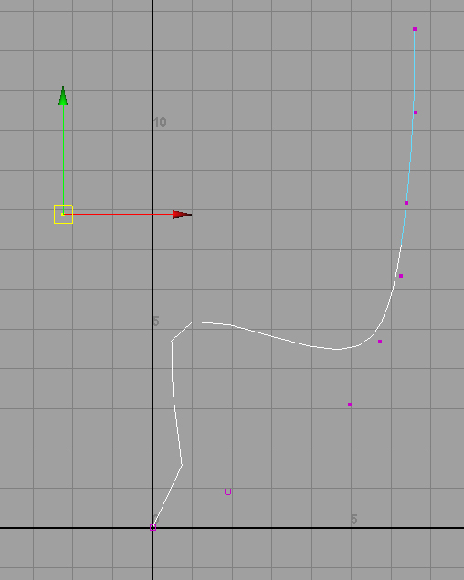
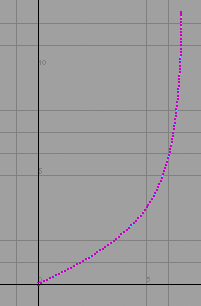
In the next picture, I blend off the imageplane. So you can better see the CV curves. Set, based on the drawing, your first CV curve, till the last point, to fit the drawing.
IMPORTANT: Dont worry about the not 100% right placed curve. You can fix this later. Based on your set points, Maya calculates the curve. In the next picture you see an easy example:
NOTE 1: Maya create ever a new curve snapped to the grid at 0,0,0!
NOTE 2: You see the first set "CONTROL POINTS" are at very different positions. I have done this, to show you how Maya calculates the curve.
IMPORTANT: Create ever your "CONTROL POINTS" exactly to the drawing because the later "REBUILD PROCESS" need this!
PICTURE:
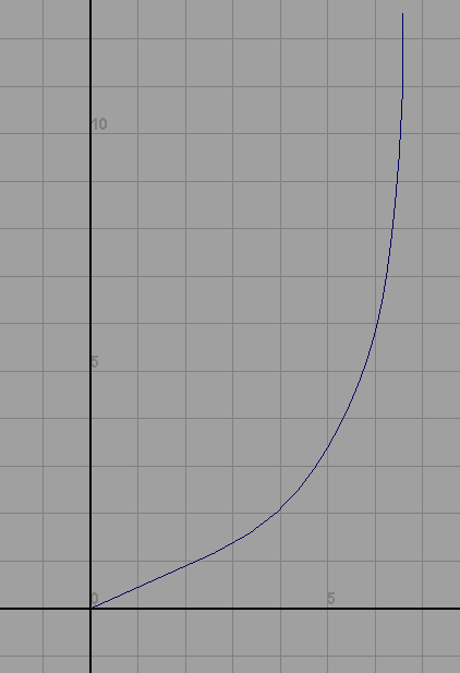
When you think the curve is OK, then please press at the keyboard "Y" and the curve is finally set. You see that the "CONTROL VERTICES" are gone and only the CV curve is visible.
PICTURE:
If you dont like the shape of your curve or did you think its need to correct the curve, please highlight it, make a mouse right click and chose "CONTROL VERTEX".
PICTURE:
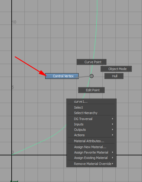
You can now move every vertex of the curve and correct its shape, to fit the drawing. When you are finished, press at the keyboard "Y" again or make an mouse right click and chose "OBJECT MODE".
PICTURE:
--------------------------------------------------------------------------------------------------------
--------------------------------------------------------------------------------------------------------
Repeat this for every curve at the drawing.
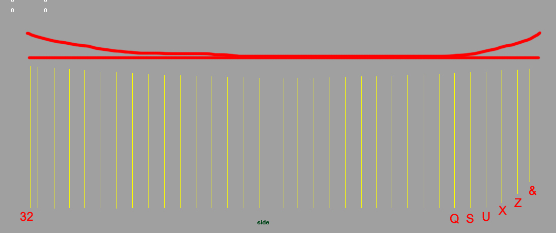
IMPORTANT 1: Create all curves at the top to the same length! Create the curve till the position the drawing is showing and then extend it to the position, the highest curve have. Why, I tell you later!
IMPORTANT 2: After finshing a curve, please move it to the right position, based on the "SIDE" drawing! For example: When you create curve "32" then move it to exactly to this position on the grid in "SIDE" view!
IMPORTANT 3: The body drawing show ships front and heck curves at different sides. When creating the CV curves, you can bypass its visual overlap in Maya when you add all finished curves into an layer and blend it out. Best method is to mirror the front drawing, so that you can setup easy at one gridside all curves. Or you create front and heck at the side, the drawing is showing, and "duplicate special" then the curve to the other side. Its your choise, how you like to do this!
--------------------------------------------------------------------------------------------------------
--------------------------------------------------------------------------------------------------------
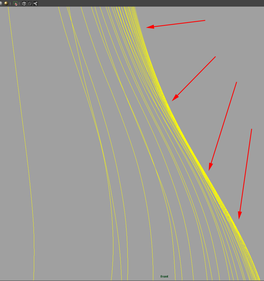
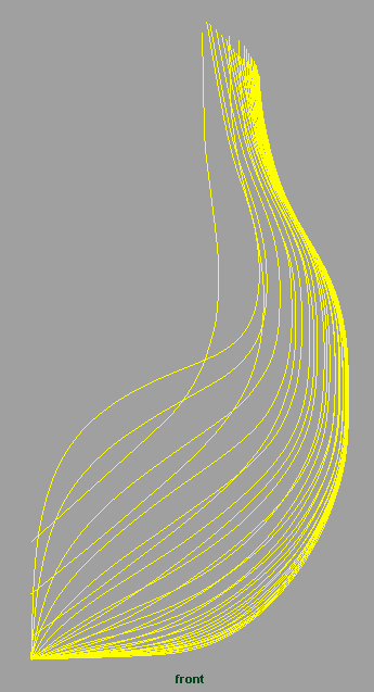
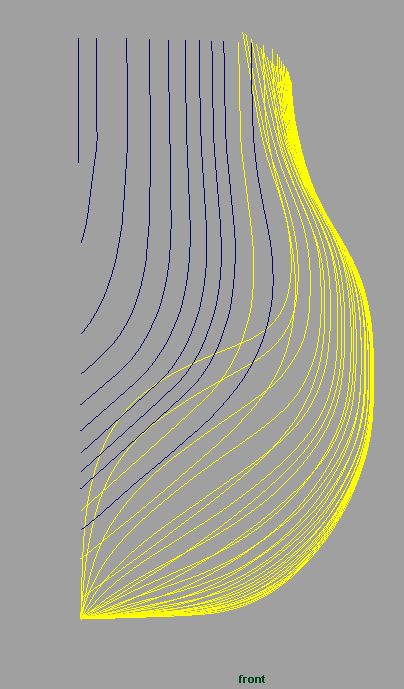
When you have finished all curves, please blend in the CV curves step by step and take a look, if the upper shapes fit good together. This is most important for the final ships shape. The next picture show you the most sensible areas. You need to enlarge your view more and more, till you like the shapes, the curves have to each other.
PICTURE:
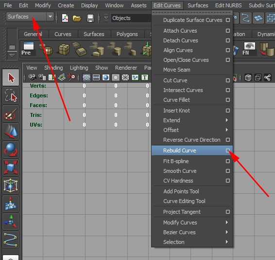
When all CV curves are done, please "REBUILD THE CURVE". Here you find the reason why to set the "CONTROL VERTEX" fit to the drawing. When you rebuild the CV curve for the later process then you need this right placement, to get no unintended dents into the curve. Remember that the CV curves shape will be definited by its "CONTROL VERTICES". Please start this command at the "OPTION BOX".
PICTURE:
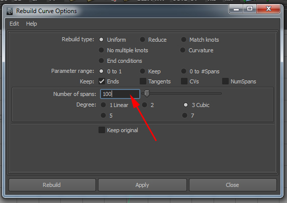
Test at the position, the red arrow is point too, what value is the best. Normally 100 - 300 should be set. This setting is important for the next step! Remember the extend curves at the top, in the creation process!
PICTURE:
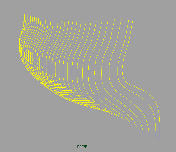
This is a good rebuild result:
PICTURE:
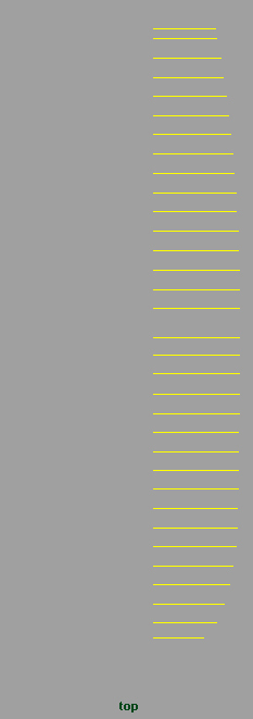
Now comes an important step! Load the side drawing with the planks as imageplane! If you dont have a plan with this, please setup in tools like photoshop the side plan you have with helpers, to show the flow of the hull planks. A good help is the deck shape.
PICTURE:
Now take CV curve by CV curve and delete all top "CONTROL VERTEX", to fit every curve to the flow of the planks. Move the imageplane a bit higher for this, to see all top ends of the CV curves at the planks shape. If a curve didnt have enougth points to delete the "CONTROL VERTICES" right, then please rebuild the CV curves with more points again!
The final result should be looking like the next picture is showing (with my hand drawn red line). The top shape must be concave after your work.
PICTURE:
PICTURE:
PICTURE:
PICTURE:
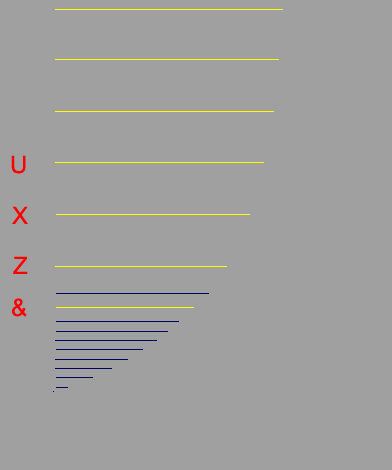
When you take a look now to your CV curves, you will notice really fast, that the whole bug is missing. For this, we now duplicate the latest CV curve (curve "&" at the drawing) and place it, based on drawings top view (imageplane!), to the best position, to extend the hull flow. Use snap to grid the curves pivot point and scale and move the CV curve till its fit to the side and top view. Its easy, belive me! You only need to copy the base CV curve and extend the bug step by step.
The final result (blue CV curves) should be looking like this:
PICTURE:
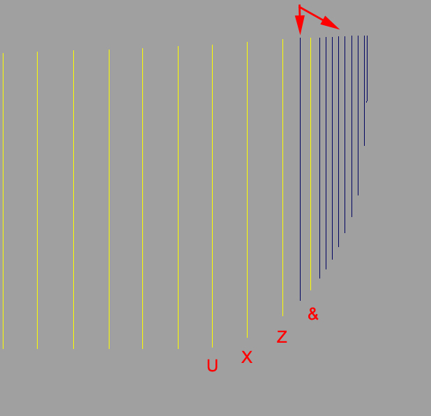
You see, that I add a curve between "shape curve "&" and "Z" and set the bugs CV curves much more close together then the original side curves. The reason behind, is to get a well shaped bug after using the "loft-extrude".
IMPORTANT: Notice that the last CV curve, you see at the next picture only as blue dot. In the picture above, its the right CV curve at the top of the bug.
PICTURE:
PICTURE:
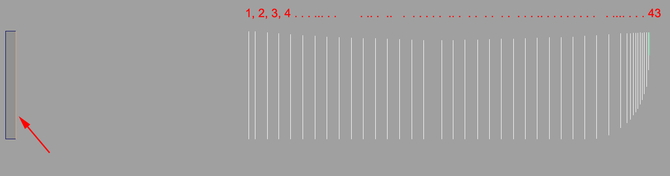
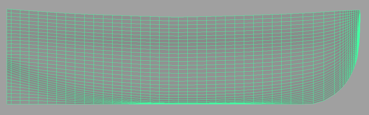
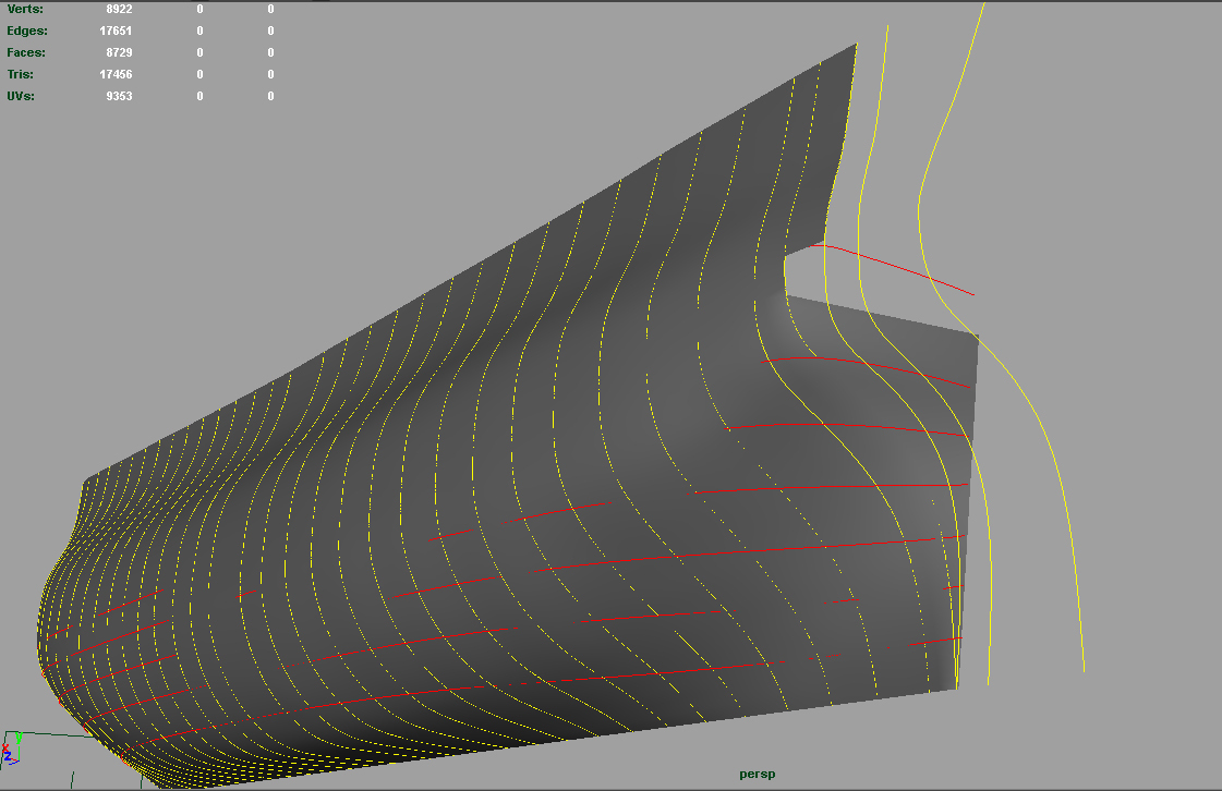
Now we want to "loft" the hull. For this, please create a simple quad polygone aproximately in the height of the first CV curve and highlight only its vertical edge (the one in direction to the CV curves). Then, please highlight in the right order all CV curves. Starting at the side with the highlighted polygon-quad-edge and highlight then curve by curve (take a look at the red numbers).
PICTURE:
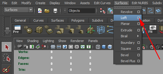
Now start the optionbox of the command "loft".
PICTURE:
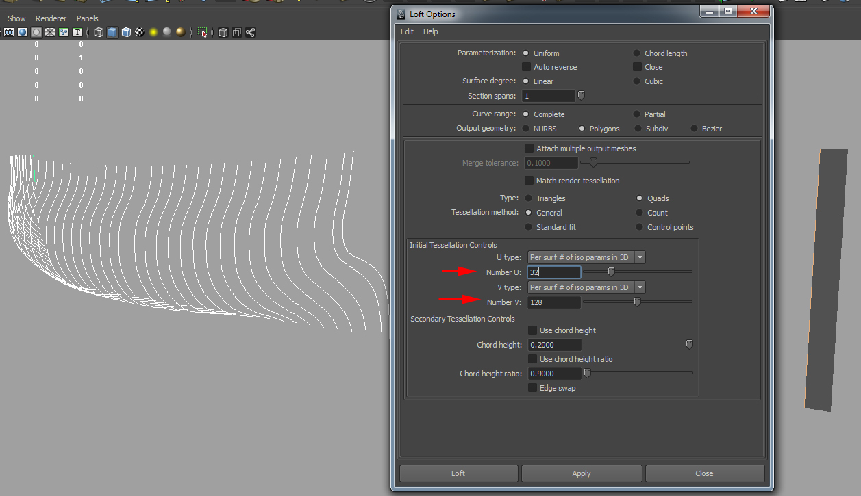
Setup the follow settings (note ALL settings) and attention then the values at the red arrows. There you setup the resolution of the final loft mesh. Try around, if you dont like the result but please ever set the resolution high. You can delete later the edgeloops you dont need:
PICTURE:
The result should looking similar to this one:
PICTURE:
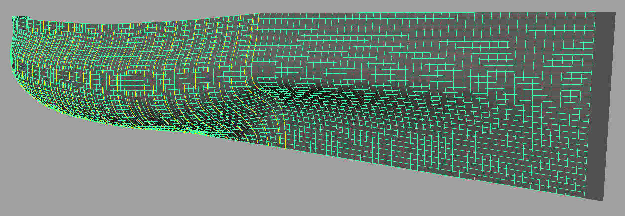
PICTURE:

Clean now the mesh. Delete the edgeloops you didnt need.
PICTURE:
PICTURE:
PICTURE:
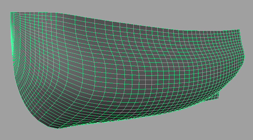
In the next step you need to create the heck. A good way is to setup the horizontal body curves from the drawing and extrude from your lofted mesh the new mesh along these. For this work a bit practice is need. Sometimes its helpful to extrude two meshes, to hold the shape close to the plan. Try around and find out whats your best way.
PICTURE:
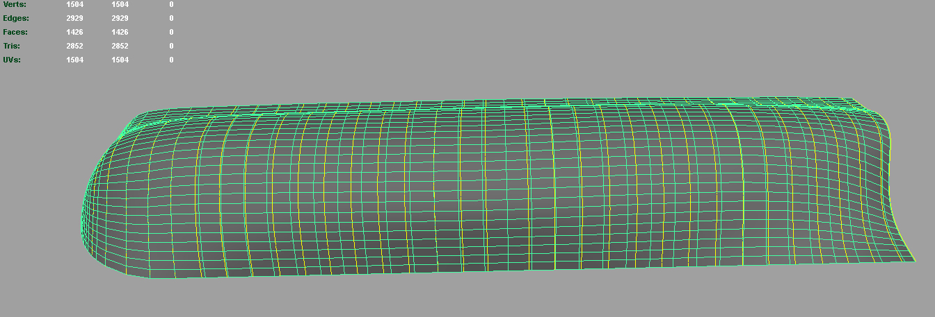
Last but not least cut now the mesh to the final body shape, to make them fit to the drawing.
PICTURE:
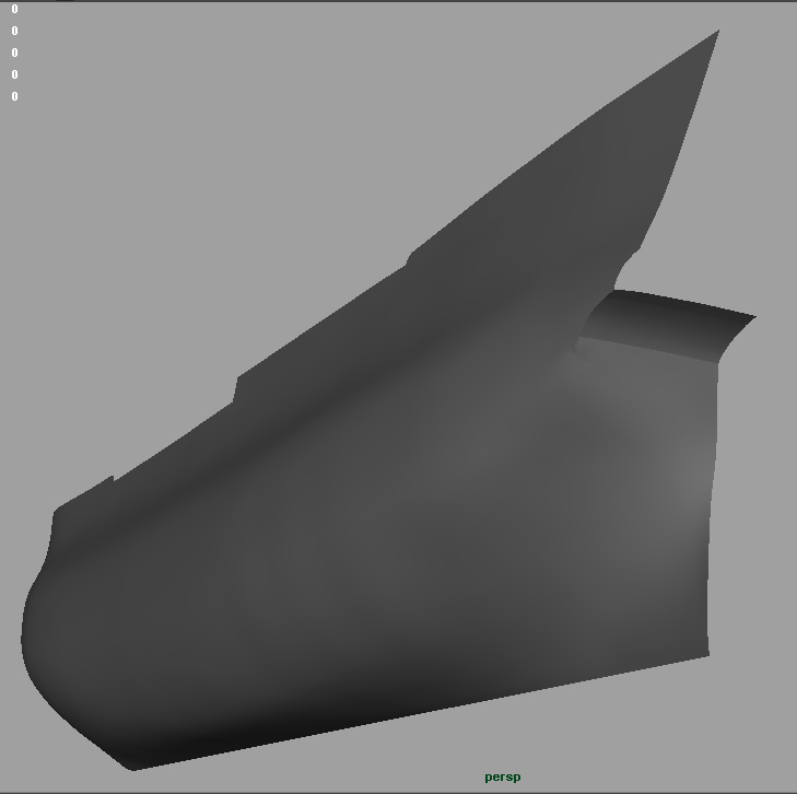
PICTURE:
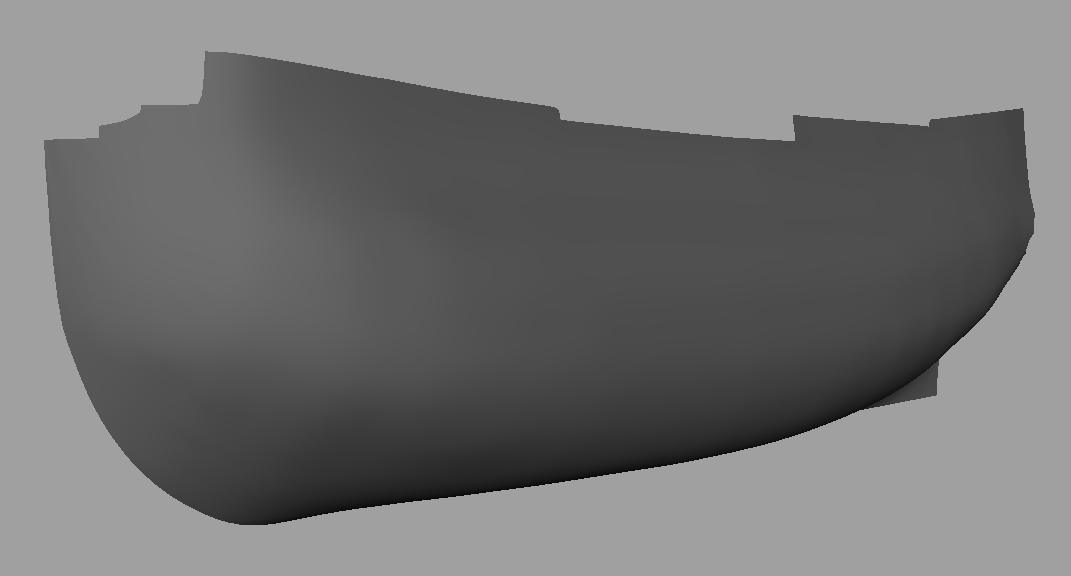
OK, well done, youre now finished with your base hull. Next steps are: UV- Map, cut in the gunports etc. and "duplicate special" to the other side.
-END-
-
