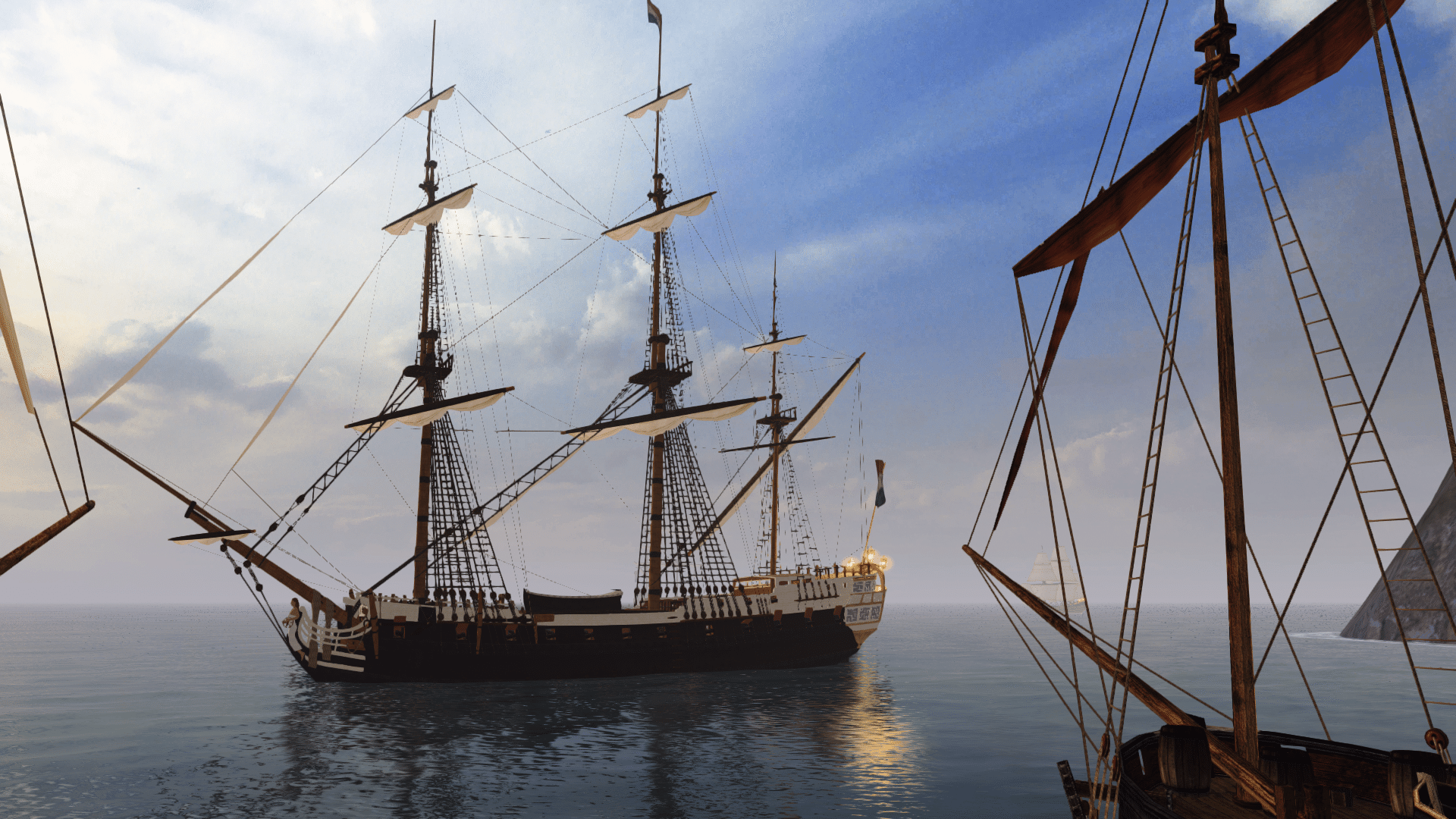
• New Horizons on Maelstrom
    Maelstrom New Horizons


    Visit our website www.piratehorizons.com to quickly find download links for the newest versions of our New Horizons mods Beyond New Horizons and Maelstrom New Horizons!

WIP HMS Bellona (1760 version)

Wow, has it really been that many months since I last posted an update? :oops:
Never mind. UPDATE TIME (though not a very exciting one this time).

I've more-or-less finished what should be the final rebuild of the hull mesh. Bear in mind that the bow and stern decorations have not been affected.
The reason I chose to rebuild it was because I realised the old mesh wasn't very good for UV mapping above the wales, because I followed Helldiver's tutorial that has the edges running parallel to the decks and never intersecting the gunports. This is fine for lower-poly models for the Storm games, but for the kind of detail we're aiming for now, it doesn't produce smooth enough results.

So here's a quick explanation of the process I used and the results it has produced.
(NOTE: Images below are NOT for showcase on ModDB and elsewhere. They would confuse people after seeing the previous WIP images.)

I started by placing a curve along the lower edge of the main wale (red curve below) and duplicated and adjusted this curve towards the top and bottom of the hull:
Bellona_WIP15.jpg

EDIT: Oops... any resemblance to the St. George's Cross is purely coincidental.
The yellow crosses represent the Edit Points of each curve, which I aligned with the hull ribs on the plans.
Above the red curve, the others are mostly parallel except for two points on the stern (circled red below), where I bent the curves to touch two corners.
Bellona_WIP16.jpg
With the curves in place, I then lofted through them from top to bottom, creating a NURBS surface instead of a polygonal mesh.
This worked well overall, except three areas around the stern (circled red below), which understandably had problems following the hull's complex shape.
Bellona_WIP17.jpg
Luckily, with a few small tweaks to the surface's control points, I managed to straighten out these areas to get the correct shape.
Bellona_WIP18.jpg
So the idea is that the final result, which follows the planking lines where needed, can easily be converted into two or more polygonal meshes: a low-poly one for the collision proxy, and a high-poly one (or ones) for the visible model. Each one will have the excess removed (especially around the bow) and other details added.

Was it worth the effort? Well, it lets me produce different LODs without needing to mess with Maya's awful smoothing options, or having to add and adjust new edge loops by hand.
And following the planking lines means I can extrude details like the wales straight from the hull mesh, rather than having to make new ones from scratch.

If any of you experts can see any problems, let me know ASAP before I commit to this hull shape and actually get on with the finer details. ;)
Again, these images are NOT for reposting elsewhere. Once I've got this hull thickened, mirrored and UV mapped, I'll add a few more details and then post some nice images.
 
That is an interesting way of modelling a hull,

Also have you thought of uploading the hull form to sketchfab so your work can be seen in 3D as this may help getting feedback on the hull form.

Regards,
 
I was thinking about that the other day after seeing some of your own work on Sketchfab. I will look into it. :)
 
Last edited:
OK, I've set up a Sketchfab account and got the Maya exporter installed and working. Nice and easy so far, though I converted the NURBS surface to polys for the export to work.
Then I went the extra mile to add proper embed support for it on this site, like so:


When you hover over the Embed (chain link) button in your model preview, copy the short URL and use the Media embed option when posting a reply here. ;)


EDIT: Due to a change on Sketchfab, I've had to change the embed settings here to use the URL that you see when viewing your own model on your Sketchfab profile.

Example for the window above: https://sketchfab.com/models/0c503bf577554998a3b22ce38f47af49
 
Last edited:
Looking good Armada,

I noticed the area at the stern post is pinched inwards which could just be with the conversion from NURBS to polys. The keel will taper from the centre, and the stern post will taper from top to bottom as well.

Usually I dont apply the tapers to the small vessels as their keels are already small, I sometimes just taper the rudder to give the illusion of taper to the stern post and keel which may be a way to avoid tapering the keel.

If you want to taper the keel, stern post this may help:
Width of Keel at centre = 1/25 x maximum breadth amidships (example: a ship with 25ft beam would have a keel 1ft wide amidships).
Taper to the bow is 10.25inches while the stern is 9.5inches

This attached scantling proportions list may also be useful, it is information from the book Construction and Fitting of the English Man of War.

Regards,
 

Attachments

  • Frame Scantling Formula Full.zip
    5.7 KB · Views: 263
Last edited:
Yeah, I didn't really notice the mistake on the stern post area until I mirrored the hull. I'll be sure to correct that.
Thanks for the info on tapering, that should be useful. :)
 
Well this definitely makes me feel better. I get sick and come back to see progress on my darlin! Good work armada!
 
I got rreally sick. And then this weekend I completely snapped on a certain person. Now everything's good and I have no stress whatsoever... Even my voice changed. :confused:

But yeah. I'm more alive than I have been in the last six years. And seeing how no one on the WT did anything... I'm going to start writing the more ddetail acts tonight or tomorrow.

Let's get this over with even If I gotta do it myself with you Dario and Mask.
 
Good to see you, mate! Glad I could help. :doff

Here's another short update. I've brought the keel from the previous hull back, added more polys towards the bow and tapered the stern post.
The hull pinching near the stern has been addressed, and hopefully looks better now.

 
Last edited:
Another quick update. This time I've been experimenting with the different NURBS > Polygons settings to see what kind of 'high-poly' hull I could produce, and settled on an option which consists of twice the divisions in both the U and V directions (horizontal and vertical). This almost seems like overkill, but the result is significantly smoother around the bow and stern where it's most noticeable.

I've already removed a couple of superfluous edge loops and merged a few vertices to get a more refined result, but I'm curious to see what you guys think.
Too many polys, or just enough? (Don't say "not enough". :p) If too many, where do you think it could lose some edge loops?


While I'm at it, could someone answer me this:
How much of the underwater hull would be painted white? The entire area below the wales (as with my original hull), or just the area below the waterline itself?
If the latter, I'll need to insert an edge loop representing the waterline, to make things easier later on.

Sorry for the boring updates, by the way. I promise that once I've got this part sorted, things will get more interesting again. ;)
 
Not enough Poly's... :razz

My Survaaw Needs to be the smoothest ship on those waters even if it wins fights by lagging out its opponents LOL:pirate41:
 
Quick first thoughts: Looks mighty good! insert the edge loop at the waterline because that will be needed for coppering, but I'm fairly certain the white would go all the way up to the wales before that was introduced.
 
Looking good! I can't seem to see the Sketchfab model, but from the preview I'd say you could easily lose a few vertical edge loops round about the waist. There's not much traverse change in that area of a ship, whereas there's lots afore and abaft.

As for the white stuff: from what I've seen, English practice tended to use it all below the wales on smaller craft, but up to the waterline only on ships of two or more decks. It's hard to find paintings in which the waterlines are clearly visible, but here are several from our time period that show the white stuff stopping at the waterline clearly:

Launch of a Fourth-Rate on the River Orwell, 1748
Bombardment of the Morro Castle, Havana, 1 July 1762
A third-rate on the stocks at Deptford, thought to be the 'Buckingham', 1752
The 'Royal George' at Deptford Showing the Launch of the 'Cambridge', 1757
The 'St Albans' Floated out at Deptford, 1747

Lastly, an interesting one showing two 6th-rates, one with a clearly marked waterline, the other without:
A Sixth-Rate on the Stocks, 1758

The majority of paintings either seem to omit the white stuff altogether or are sufficiently ambiguous to be of no help; the last is the only clear depiction I've spotted from the era showing white stuff to the wales.

Furthermore, most -- though not all -- images pulled up in a Google search of models of the pre-coppered Bellona seem to have the white stuff end at the waterline. Hardly a definitive test, but clearly demonstrative of a general consensus.

If anyone can find clear examples of larger ships of the period whiting everything below the wales, please share! Just finding one would show that anything goes on this regard, as opposed to sample bias in painters.
 
Looking good,

At the hull around counter there may be a need for a few adjustments of the vertices as it seems to be indented (if you follow the top edge of the counter to the side you should see what I mean). There is also a small anomaly which could just need triangulating (counting the top edge of the counter as one, six lines down then follow to the side should locate it).

Also it may be a good idea to have the polygon smoothing group of the counter different from the rest so as to define it more.

Also out of curiosity what is the triangle count?

Regards,
 
Back
Top